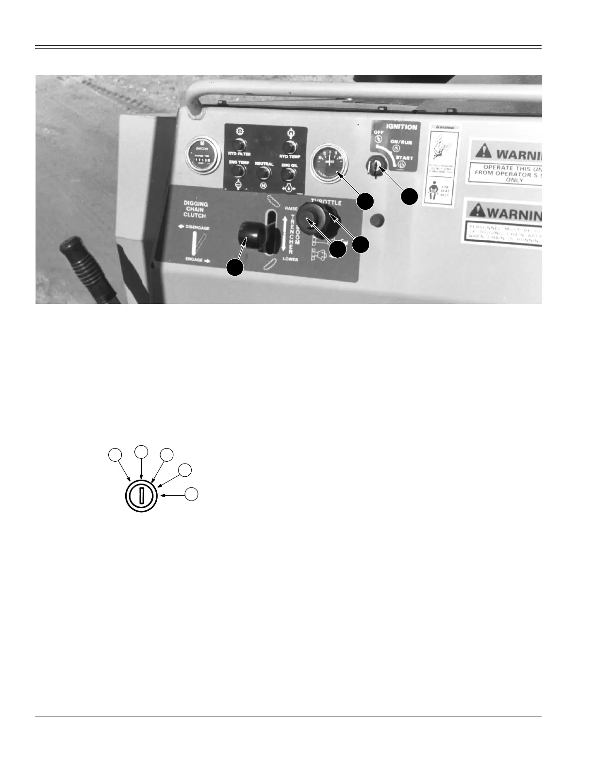
INSTRUMENTS/CONTROLS
AU103170 H5B 18
A27440
8. AMMETER 9. KEY (IGNITION) SWITCH 10. TRENCHER BOOM LEVER 11. THROTTLE 12. THROTTLE LOCK
8. AMMETER
This gauge indicates the rate of charge or discharge for
the battery. The positive (+) side indicates charge and the
negative (-) side indicates discharge. If the gauge
indicates high charge (+) or discharge (-) during machine
operation, stop the engine and check for the problem.
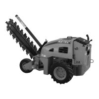
9. KEY (IGNITION) SWITCH
This switch has five positions:
BS99C083
1. ACCESSORY (Position not shown on decal) - This
position will energize the hydraulic cooler fan and
plow cooler fan.
2. OFF - Use this position to deenergize the electrical
system to stop the engine and to remove the key.
3. ON/RUN - This position will energize the electrical
system. The key will return to this position after you
release the key from START.
4. TEST (Position not shown on decal) - Turn the key
half the distance between ON/RUN and START to test
the warning lamps. All warning lamps must
illuminate.
5. START - Turn the key to this position to actuate the
starter motor to start the engine.
NOTE:
See STARTING THE ENGINE in this manual for the
correct procedure to start the engine. Before the engine is
started, make sure you are seated in the operator’s seat
and ALL warning lamps illuminate.
10. TRENCHER BOOM LEVER
This lever has two functions, RAISE and LOWER.
Pull the lever all the way up to raise the trencher boom.
Push the lever all the way down to lower the trencher
boom.
11. THROTTLE
Push the button at the center of the knob and pull to
increase engine speed. You can rotate the knob to make
small adjustments to the engine speed. Rotate the knob
counterclockwise to increase engine speed and clockwise
to decrease engine speed. Push the button at the center
of the knob and push the knob in to decrease engine
speed (see Ref 12 for additional information).
IDLE - Pushed in all the way
1/4 THROTTLE - Pulled out approximately 13 mm (1/2”)
1/2 THROTTLE - Pulled out approximately 25 mm (1”)
3/4 THROTTLE - Pulled out approximately 38 mm (1-1/2”)
FULL THROTTLE - Pulled all the way out
12. THROTTLE LOCK
Use the throttle lock to hold the throttle in position during
machine operation. Rotate the throttle lock clockwise to
HOLD and counterclockwise to RELEASE the throttle
(when the machine is not in use the throttle lock should
be tightened to prevent moisture from entering the
cable).
9
8
11
10
12
1
2
3
4
5