OPERATING INSTRUCTIONS
AU103170 H5B 32
Teeth
The most important parts of the trencher are the teeth.
The type of teeth that you select and the arrangement
you use makes a big difference in the digging efficiency
and tooth life.
Cupped Teeth
These teeth are the best in cutting light to medium soil.
The cupped design of the tooth cuts the soil and then
moves the soil up and out of the trench.
B4122788W
Rock and Frost Teeth
Use these teeth when the ground is very hard, rocky or
frozen. Also use the rock and frost teeth when cutting
through blacktop.
B4122888W
Tooth Arrangements
The tooth arrangement is where and how each tooth is
attached to the digging chain. The arrangements shown
in the specifications section of this manual are for normal
soil conditions. Use the following rules when selecting
other tooth arrangements.
1. Install teeth of the same width at equal spaces
around the chain.
2. Use less teeth on the chain when operating in wet
clay or gumbo.
3. Install more teeth when working in sandy loam or
rocky ground.
4. Use dirt drags in sand or loose soil.
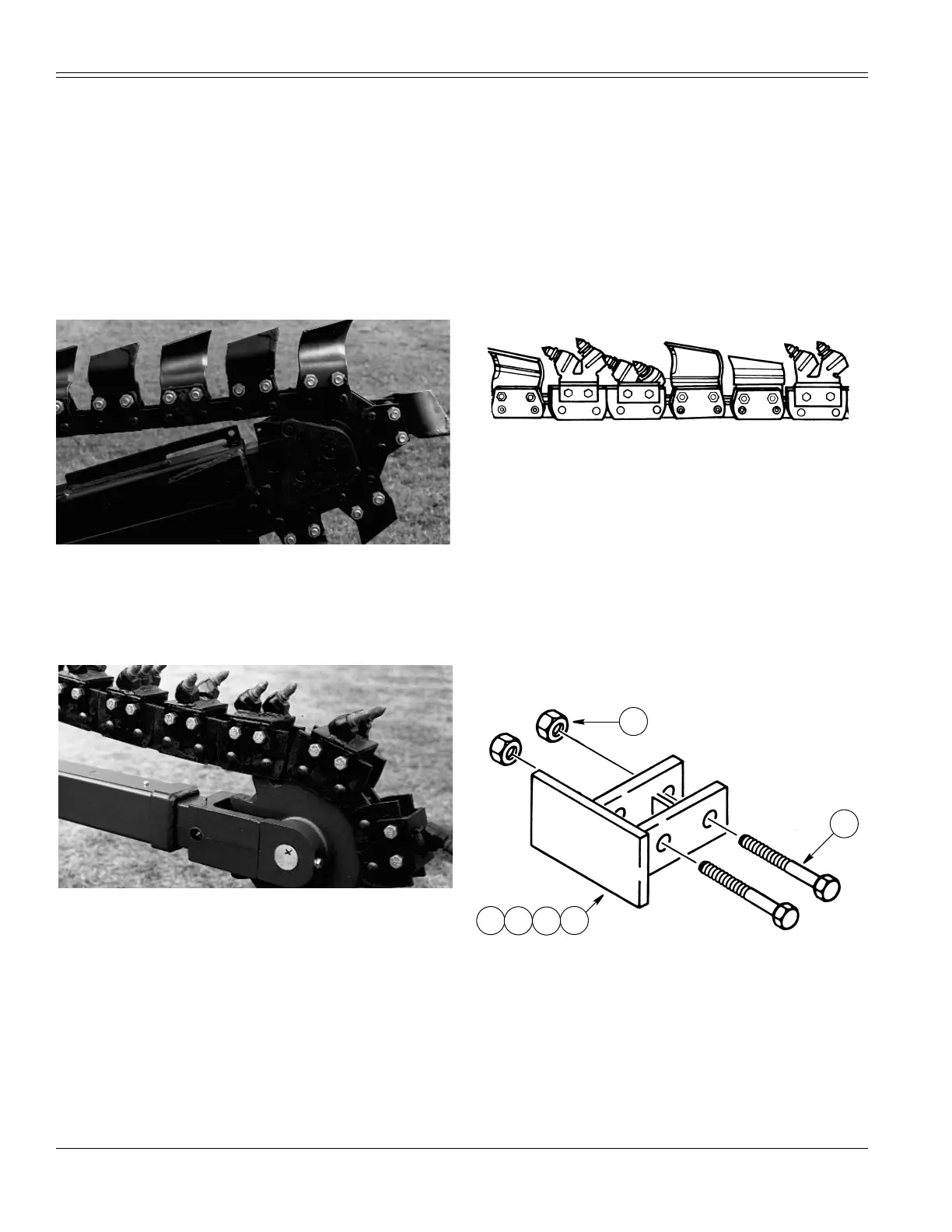
Tooth Combinations
The two types of teeth and dirt drags can be used in
several ways to increase productivity in different digging
conditions. The rock and frost teeth give good penetration
and the cupped teeth help with soil removal. Try several
combinations to find the one best suited for your area.
B2226A88J
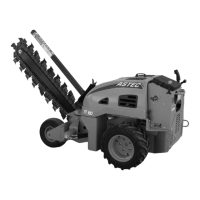
Drag Plates
The drag plates (a minimum of two) must be installed at
approximately equal distance around the digging chain.
Remove the tooth that follows a wide tooth on the digging
chain and install the drag plate.
Do not install drag plates on anti-backflex chains or use
with rock and frost teeth.
NOTE:
It is important to have a left hand tooth behind
one drag plate and a right hand tooth behind another
drag plate. If necessary, remove the tooth behind the
drag plate and install the correct tooth
.
B861179J
1. BOLT 15.87 X 88.9 MM (5/8 X 3-1/2 INCH)
2. LOCKNUT 15.67 MM (5/8 INCH)
3. 127 MM (5 INCH) DRAG PLATE (USED ON 152 MM (6 INCH) CHAIN
4. 178 MM (7 INCH) DRAG PLATE (USED ON 203 MM (8 INCH) CHAIN
5. 229 MM (9 INCH) DRAG PLATE (USED ON 254 MM (10 INCH) CHAIN
6. 279 MM (11 INCH) DRAG PLATE (USED ON 305 MM
(12 INCH) CHAIN
6
5
3
4
2
1