52
ORTHOGONALITY
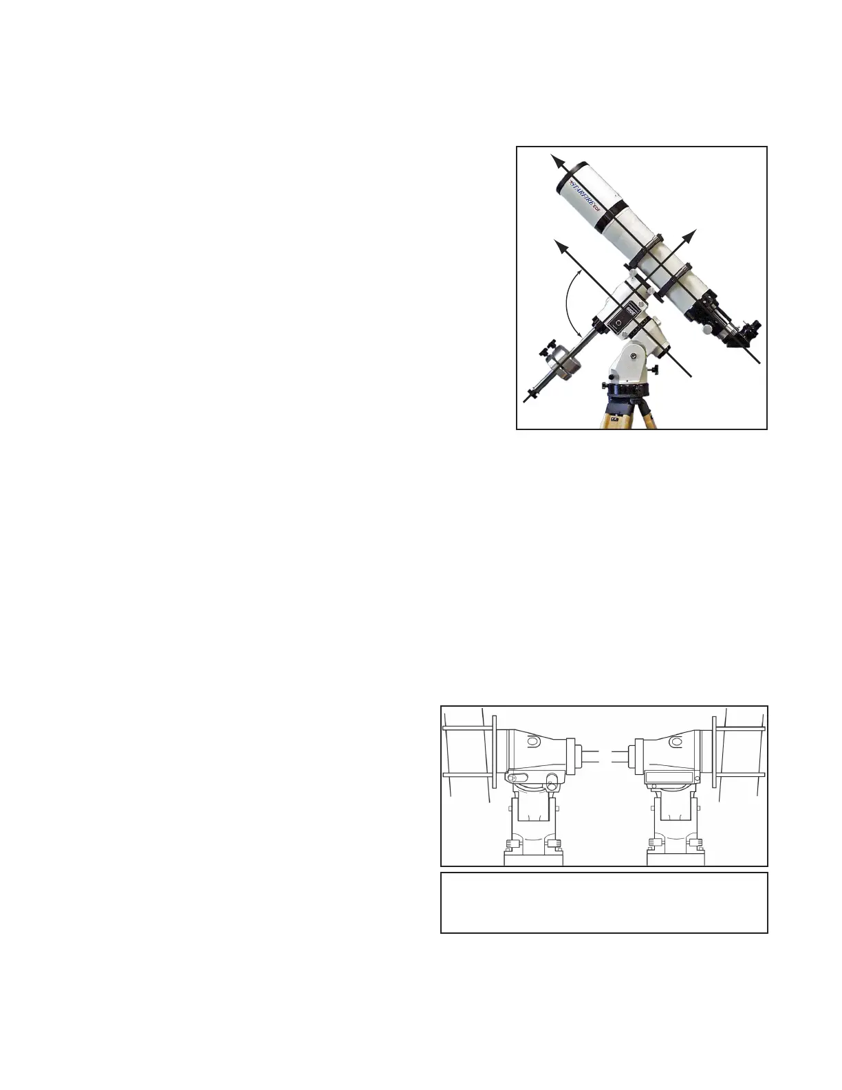
A telescope is said to be orthogonal when its optical axis is exactly 90 degrees from the declination axis as shown in the
photo. In Alt-Az fork mounts, orthogonality is not an issue. Pointing is straightforward, the scope never has to ip sides
and the mount does not need to be polar-aligned. However, in German equatorial mounts, a non-orthogonal telescope will
cause errors in any routine that uses the scope for polar alignment (such as the N Polar Calibrate routine) and will reduce
the pointing accuracy of the system by exactly twice the orthogonal error.
Telescope orthogonality requires that two conditions be met:
1. The R.A. and Dec. axes of the mount are at precise right angles to each
other. Astro-Physics mounts are very accurately machined and full this
condition.
2. The optical axis of the telescope must be parallel to the R.A. (polar) axis.
Some of the factors which could affect this condition include:
a) Improperly machined rings.
b) Wedge in the mounting plate or brackets.
c) Incorrect position and tilt of a diagonal mirror or diagonal assembly
that is not machined square.
d) Set screws in focusers, diagonals or adapters which tilt the optical
axis.
e) Die-cast tube assemblies that lack the precision squareness of a CNC machined part. The tube points in one direc-
tion while the optics can point several degrees off in another direction.
f) Diagonal displacement or tilt in a Newtonian.
g) Mirror shift in a catadioptric. The optics are not tied down to a reference plane, but can move around and point in
different directions depending on focus position.
h) Collimation adjustment. There is enough freedom in the tilt of a secondary mirror to allow the image to be moved
completely out of the eyepiece eld. Therefore, collimating the scope may disturb or change orthogonality.
Whatever the reason, orthogonality can be easily checked and adjusted, if needed.
Check Orthogonality
The optical axis must be parallel to the polar axis and 90 degrees to the declination axis
To do an orthogonal check, the mount should be close to
polar aligned, however the alignment does not need to be
perfect. Next, you need to slew between two stars that are
straddling either side of the meridian.
For instance, in early summer at 9 p.m. (northern
hemisphere), the constellation Boötes is straight up and
Alpha Boötes (Arcturus) and Epsilon Boötes are on either
side of the meridian. Follow this procedure using a reticle
eyepiece:
While Arcturus is not a suitable star to use in the N-polar
alignment routine, it works well in this application.
1. From Objects menu, select “8=Tours”.
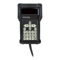
Exaggerated illustration of error caused by mounting rings with varying thickness at base of ring. Shows how scope will
not point to desired target and the displacement that will occur on either side of mount.
2. Choose “1=Stars/Constell” and scroll to “Cons:Boo”. (If the stars you want to use are listed in the common star
names list, you can choose “5=Strs” from the Objects menu and select the stars from that list).
90°
Exaggerated illustration of error caused by mounting
rings with varying thickness at base of ring. Shows
how scope will not point to desired target and the
displacement that will occur on either side of mount.