60
UNDERSTANDING THE KEYPAD AND GTO CONTROL BOX
FUNCTIONS
Functions of the GTO Servo Control Box
These notes apply to the GTOCP1, GTOCP2, GTOCP3 and GTOCP4 models of the control box. The model number is
silk-screened on the face plate of the box.
The main function of the servo control box is to drive the R.A. and Dec. motors. The motors are DC servos with built-in
shaft encoders. The rotation rate of the motors is controlled with a servo feedback loop. The servo looks at the return
pulses from the shaft encoders and adjusts the current to the motor so that the rate is identical to the commanded rate (i.e.
from 0.25x sidereal to 1200x sidereal). The servo is digitally controlled, and the shaft position is updated at a rate of 2000
times per second.
The central computer in the servo is a microprocessor that converts input commands to electrical signals to move the
motor. The input commands are in the form of the AP protocol, e.g. :Sr 02:45:32.5# which would dene a move position
of 2hr 45min 32.5sec in right ascension. The microprocessor converts those numbers to specic shaft angles of the two
axes, and determines whether the telescope should access that position from the east side or west side of the mount. The
servo responds to commands to move in R.A. or Dec. when any of the 4 buttons are pushed, according to the rate set on
the Keypad (from 0.25x to 1200x). The servo will also initiate movement in the 4 directions from inputs sent to the CCD
guider port at rates set by the Keypad, typically 1x, 0.5x or 0.25x the sidereal rate.
The servo microprocessor stores vital date, time and location information sent to it from the Keypad, or a planetarium
program via one of the input ports. It stores worm periodic error information (PEM) so that it can be played back when
required for high-accuracy tracking.
The main function of the servo control box is to convert input data from the Keypad or a planetarium program (in the form
of the AP protocol) to electrical signals to the motor to produce the desired motor motion and to result in the telescope
pointing at the desired object in the sky.
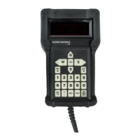
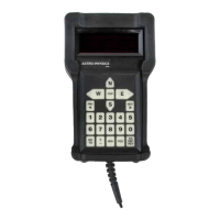
Functions of the Keypad
The Keypad controller is really a small hand held computer with planetarium software. It has a database for tens of
thousands of objects that can be accessed by Keypad entry or scrolling through a menu.
To orient the system properly with respect to the sky requires date, time and location information. The Keypad contains
an accurate date and time clock powered by a lithium battery. Together with the location data that is entered by the user,
the Keypad uses this information to calculate what part of the sky is up at any given time. The Keypad also sends this
information to the servo controller to calculate where the horizon limits are, and where the meridian line is located. This
prevents the scope from pointing into the ground and allows the servo to do a meridian swap so the tube assembly does
not dive under the mount and hit the pier.
The main function of the Keypad is to send R.A. and Dec. numbers to the mount for the objects that the user enters
into the Keypad. This is exactly the same as the functions of a typical planetarium program. In fact, most of the Keypad
functions can be replaced with those contained in PulseGuide by Ray Gralak, or an advanced planetarium program, like
TheSky6™ or TheSkyX™ from Software Bisque or StarryNight Pro Plus™ from Imaginova. You can therefore disconnect
the Keypad entirely from the mount without losing any of the functions of the mount including parking, jogging, centering or
moving to various parts of the sky. You can also control things like focus motors and reticle brightness from your desktop
computer. Not all planetarium programs support all of these functions; please check the features of the program you are
considering.
We have separated the functions of the servo control box and Keypad to allow for maximum exibility to the user.
The servo is a stand-alone unit that can be controlled entirely by the Keypad, by a desktop computer with a suitable
planetarium program without the Keypad, or with both Keypad and desktop attached.
Upgrading the GTO Servo Control Box
Upgrades to the logic of the GTO control box (GTOCP1, GTOCP2 or GTPCP3 models) are made by installing a new ROM
chip, since the chip is housed in a removable carrier, the old one can be popped out easily and the new one eased into
place. All upgrades to the GTOCP4 control box are accomplished through an internet download.