Chapter 4 Digital Output Settings (DIGITAL OUTPUT)
61
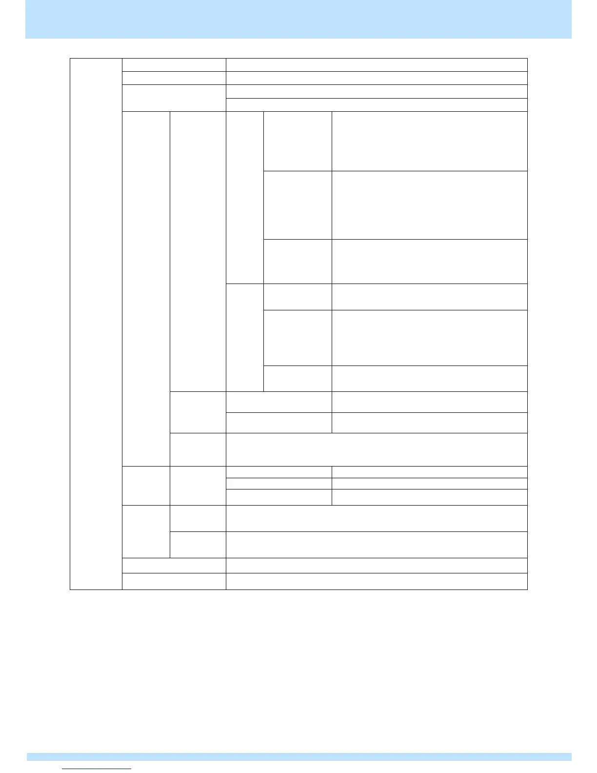
● Specifications
VESA DisplayPort Standard Ver1.2a
<For RGB/YCbCr444>
6 / 8 / 10 bit: 25 to 340 MHz
<For YCbCr422>
6 / 8 / 10 bit: 25 to 340 MHz
12 bit: 25 to 320 MHz
<For RGB/YCbCr444>
6 / 8 bit: 50 to 680 MHz (600 MHz) (*2)
10 bit: 50 to 680 MHz (576 MHz) (*2)
<For YCbCr422>
6 / 8 / 10 bit: 50 to 680 MHz (600 MHz) (*2)
12 bit: 50 to 640 MHz (600 MHz) (*2)
<For RGB/YCbCr444>
6 / 8/ 10 bit: 100 to 1200 MHz
<For YCbCr422>
6 / 8 / 10 / 12 bit: 100 to 1200 MHz
<For RGB/YCbCr444>
6 / 8 bit: 50 to 600 MHz
10 bit: 50 to 576 MHz
<For YCbCr422>
6 / 8 / 10 / 12 bit: 50 to 600 MHz
6 bit, 8 bit, 10 bit, 12 bit
RBR : 1.62 Gbps
HBR : 2.7 Gbps
HBR2 : 5.4 Gbps
20 to (1/2 of sampling frequency) Hz
DPCD, E-EDID: Ver1.4, MCCS (DDC/CI): Ver1.1
3.3 V / 500 mA with each channel
*1 For details, refer to “4.2.4 DisplayPort data transfer method”.
*2 The values within () are the dot clock upper limit values when one image is output (rendered) with one connector.
*3 The sending of Audio InfoFrame and Channel Status Bit is not supported. Also, audio output is not supported when signal output
in the MST mode.