Chapter 4 Digital Output Settings (DIGITAL OUTPUT)
82
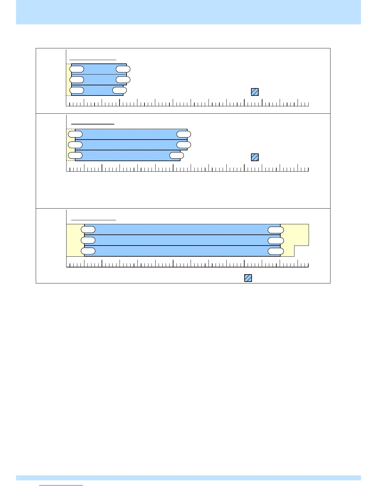
4) When the video width is 12 bits
25M 340M
340M
320M
25M
25M
11/12Bit
9/10Bit
8Bit
ColorDepth
0.1MHz 400MHz 800MHz 1200MHz 1360MHz1000MHz600MHz200MHz
Color Depth < Video Width (=12Bit)の場合、
下位にはデータ"0"が付加されています。
シングルクロックモード
データが切り捨てられます
680M
680M
640M
50M
50M
50M
11/12Bit
9/10Bit
8Bit
ColorDepth
400MHz0.1MHz 800MHz 1200MHz 1360MHz1000MHz600MHz200MHz
データが切り捨てられます
Color Depth < Video Width (=12Bit)の場合、
下位にはデータ"0"が付加されています。
デュアルクロックモード
The above displays the dot clock upper limit values when one image is output with two connectors (split rendering).
The dot clock upper limit values when one image is output with one connector are 8 bit: 600 MHz, 9/10 bit: 576 MHz, and
11/12 bit: 480 MHz.
100M
100M
100M11/12Bit
9/10Bit
8Bit
ColorDepth
400MHz0.1MHz 800MHz 1200MHz 1360MHz1000MHz600MHz200MHz
データが切り捨てられます
Color Depth < Video Width (=12Bit)の場合、
下位にはデータ"0"が付加されています。
1200M
1200M
1200M
クアッドクロックモード
When color depth < video width (= 12 bit), "0" data
is added at the lower level.
When color depth < video width (= 12 bit), "0" data
is added at the lower level.
When color depth < video width (= 12 bit), "0" data
is added at the lower level.