Do you have a question about the Atal AT 505 and is the answer not in the manual?
The ATAL Gas Analyser AT 505 is a PC-based, four-part (with an optional NOx sensor) exhaust gas analyzer designed for the maintenance and inspection of spark ignition engines. It measures HC, CO, CO2, O2, and NOx concentrations, and calculates COcor and the coefficient of air redundancy (lambda). The device also measures engine speed and oil temperature, which are essential for statutory MoT test procedures. Measured data can be printed as partial measurements or as an MoT test certificate. The AT 505 is approved for Car and Light Commercial Vehicle Testing, covering Class III (3-wheeled vehicles up to 450 kg unladen weight), Class IV (cars, taxis, minibuses, ambulances up to 12 passenger seats, goods vehicles not exceeding 3000 kg DGW, motor caravans, and dual-purpose vehicles), and Class VII (goods vehicles over 3000 kg up to and including 3500 kg DGW).
The measuring principle for CO, HC, CO2, O2, and NOx complies with OIML R 99 class 0. CO, HC, and CO2 concentrations are measured using non-disperse light attenuation in the infra-red area (NDIR), with signals compensated for temperature and barometric pressure changes. O2 and NOx concentrations are measured with electro-chemical sensors, which have a limited service life (typically at least six months). The analyzer automatically monitors these sensors and reports when renewal is required.
Function Properties:
General Information:
Host Computer Requirements:
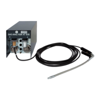
The AT 505 is part of the modular Multi-Diag system. It connects to a PC (or laptop) via a serial cable for data processing and printing. The device operates in a vertical position to prevent moisture from condensing in the rough filter.
Front Panel Components:
Software Installation and Configuration: The software is installed from a CD or downloaded from www.atal.cz. The installation wizard guides the user through the process, including setting up communication ports, language, monitor resolution, and enabling/disabling peripheral equipment like the Universal Speed/Temperature Sensor, Motortester, Minitester, or Multi-Diag. Administrator rights are required for configuration under Windows 2000/XP/Vista.
Device Start-up and Operation: After connection and configuration, the device undergoes initialization and optical bench heat-up. A leakage test is performed automatically once a day, requiring the probe to be removed from the exhaust and a red seal fitted. The analyzer automatically creates a vacuum to detect leaks. If the test fails, gas testing is disabled until the leak is fixed. The optical bench resets automatically at 15-30 minute intervals to maintain measurement accuracy.
Measuring Engine Speed and Oil Temperature:
Dwell Angle and Ignition Advance Measuring: These functions are available with Multi-Diag Scope, Motortester, or Minitester extensions. Dwell angle is measured via a voltage probe connected to the primary coil winding. Ignition advance is measured using an ignition sensor and another probe (induction, semiconductor, or stroboscope).
Printing Values: The print queue stores individual measurement records, which can be printed as desired. The F2 button adds screen data to the queue, and the F5 button deletes all data.
Emission Test: Launched by pressing F4, this mode performs an MoT emission test, requiring the Speed Sensor and Engine Temperature Sensor to be correctly connected, set, and synchronized.
Error Alerts: All errors are displayed on the PC screen and indicated by the status LED. An information panel provides further details and suggested measures to be taken.
The AT 505 is designed for minimal maintenance, with a focus on protecting the inlet from contamination.
Water Condensation Prevention: The device reports an error if intake probe pressure drops, indicating a choked probe or water intake. It actuates valves and pumps in cycles to reduce underpressure and prevent water penetration into the optical bench.
Coarse Filter Inspection and Cleaning: The sintered bronze grain coarse filter (F1) can be cleaned by washing in spirit, rinsing with clean water, and blowing through with pressurized air.
Fine Filter Inspection and Renewal: The paper fine filter (F2) must be replaced when contaminated. Its lifetime varies from 50 emission tests (with catalyst engines) to as few as 5 tests (with poor condition or two-stroke engines).
Oxygen Sensor Check: The analyzer automatically monitors the O2 sensor's functioning. A warning is displayed if the sensor is no longer in order or nearing the end of its service life. A new sensor has at least 12 mV; values below 5 mV indicate poor condition and lock measurement. Only an authorized service technician can replace the oxygen sensor.
Calibration and Service: The gas analyzer should be calibrated every 6 months by a UKAS approved calibration service.
| Brand | Atal |
|---|---|
| Model | AT 505 |
| Category | Measuring Instruments |
| Language | English |