Chap. I - Gas Analyser
Gas-manual-en.docx — 23 —
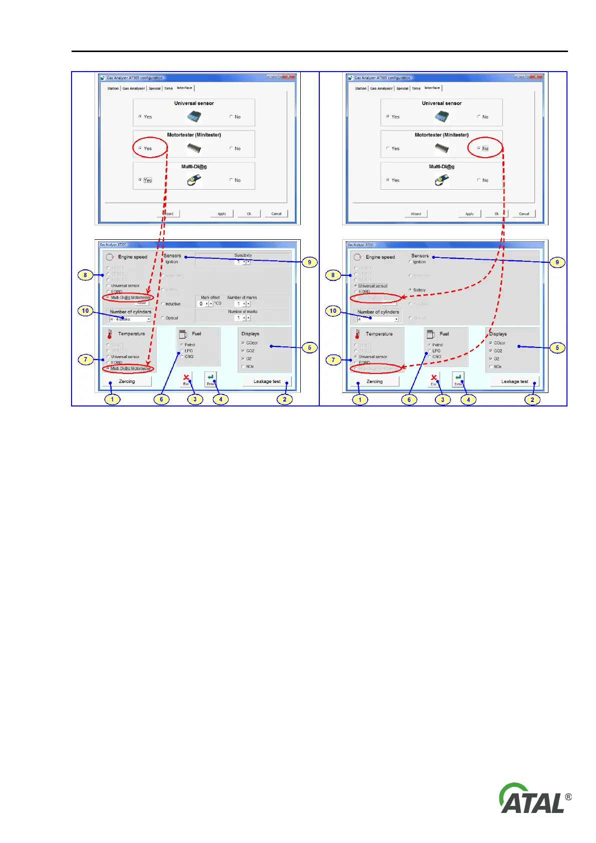
Fig. 46 – Setting some parameters of the program depending on
the switching peripheral equipment on or off (see Configuration in
Chap. I - 8.1.5 / Fig. 20). In this case, Motortester is used.
Fig. 47 – Setting some parameters of the program depending on
the switching peripheral equipment on or off (see Configuration in
Chap. I - 8.1.5 / Fig. 20). In this case, Motortester is not used.
1 - Button: Start optical bench reset
2 - Button: Start leakage test
3 - Button: Exit setup without saving changes
4 - Button: Exit setup and save changes
5 - Selection of gases to be displayed
6 - Selection of fuel for which the lambda coefficient will be calculated
7 - Selection of sensor from which the engine temperature will be read
8 - Selection of sensor from which the engine speed will be read
9 - Setup of individual probes
10 - Setup of number of cylinders or of engine type (2 stroke, 4 stroke)
12. ENGINE SPEED MEASURING
The measurement can be done by one of the following devices:
12.1 UNIVERSAL SPEED SENSOR
The measuring is carried out by connecting a suitable cable to the battery of the vehicle. There are two options to
select from:
• Connect it to the auxiliary power outlet (cigarette lighter socket)
• Connect it to the vehicle’s battery terminals: Red terminal is + pole; Black terminal is – pole
• Ignition sensor