Chap. I - Gas Analyser
Gas-manual-en.docx — 6 —
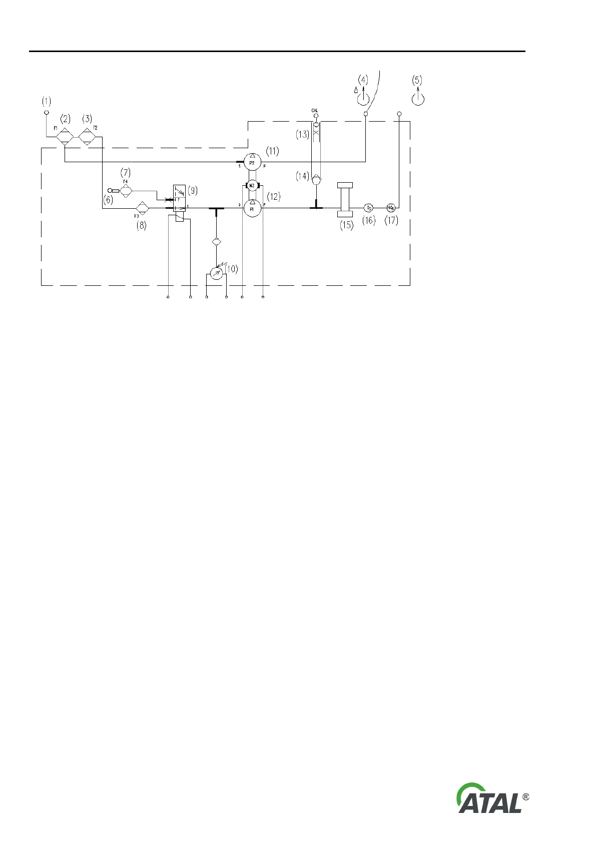
Fig. 3 – Scheme of pneumatic part
12- Main pump (P1) – measured gas
4- Condensate drain outlet
13- Pressure reduction – inlet of calibration gas with pressure reduction
6- Air intake (for zeroing)
7- Activated carbon filter (F4)
8- Fine safety filter (F3)
17- Nitrogen sensor NOx (optional)
6. MEASURING PRINCIPLE
The measuring principle for CO, HC, CO
2
, O
2
, and NO
X
complies to the requirements OIML R 99 class 0. In the
case of CO, HC, and CO
2
, it is through non-disperse light attenuation measuring in an infra-red area (NDIR).
Concentration of the three gases is measured in separate measuring cells. Signals obtained from the detectors
are then compared with a reference signal. Results are compensated for temperature and barometric pressure
changes.
O
2
and NO
X
concentration measurement is done with electro-chemical sensors. The service life of these sensors
is limited, and depends on the duration and level of concentrations, particularly of HC and Pb (from lead petrol
detergents), which they are exposed to. Normally the service life should be at least six months. The Gas Analyser
automatically monitors the sensors and reports when have require renewal.
A diagram of lambda dependency of individual gas compounds in exhaust gases is shown in Fig. 4
. The richness
of the fuel mixture is expressed by air redundancy coefficient
λ. This diagram illustrates model emission behaviour
of a non-catalyst engine.