Chap. I - Gas Analyser
Gas-manual-en.docx — 4 —
The gas analyser is a four-part (optional five-part) analyser of exhaust gases, to be used for measurement and
adjustment of petrol, LPG, and CNG engines, and for controlling emissions of those engines according to relevant
national regulations. It can measure HC, CO, CO
2
, O
2
, and NO
X
concentrations, and calculate CO
cor
and the
coefficient of air redundancy λ from those values. Furthermore, it measures engine speed and oil temperature for
use during statutory MoT test procedures. The measured data can be printed by the printer as partial
measurements or as an MoT test certificate.
Mechanical construction is described in Chap. I - 5.
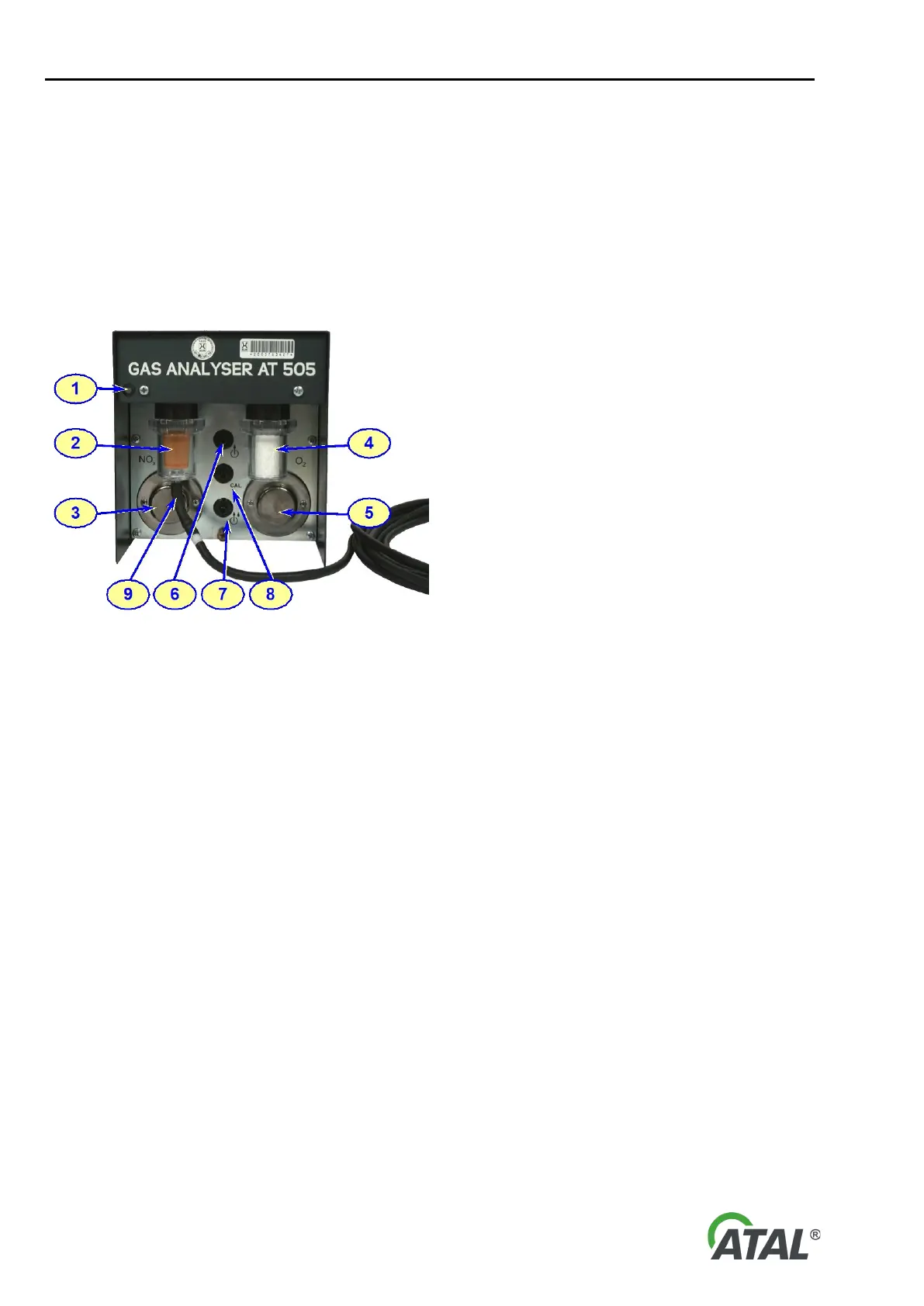
4.1 FRONT PANEL
Fig. 1 – View of the front panel of the Gas Analyser
1 - Status LED:
OFF = the power supply is not connected, or the Gas Analyser AT505 software on the PC is not running
and communicating with the Analyser.
Red = the power supply is connected, but the communication cable is not connected to the PC or the PC
is not switched on
Orange = the analyser is ON, but inactive, heating up may be in process or it may be indicating a fault
Green = the analyser is ready to use
2 - Coarse filter (F1)
3 - Nitrogen sensor (NOx) (optional)
4 - Fine filter (F2)
5 - Oxygen sensor (O2)
6 - Exhaust gas outlet
7 - Condensate outlet
8 - Calibration gas inlet
9 - Exhaust gas intake