Chap. I - Gas Analyser
Gas-manual-en.docx — 16 —
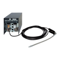
Fig. 33 – The status of the communication ports after connection of the testing device to a computer serial port connector
The status of the communication cables is as follows: green = OK
red = no connection
Note: Some devices are functional with only the Rx-Tx connections made (e.g. Opacimeter AT605).
Remove the testing device and plug in the analyser. It is important to set the detected port number for the
analyser in the Configuration Program (for starting the program see Chap. I - 8.1.1 and Fig. 16 - note 2) or in
the Program Configuration Wizard (see Chap. I - 8.1.6, Fig. 22).
8.2 PROGRAM CONTROL
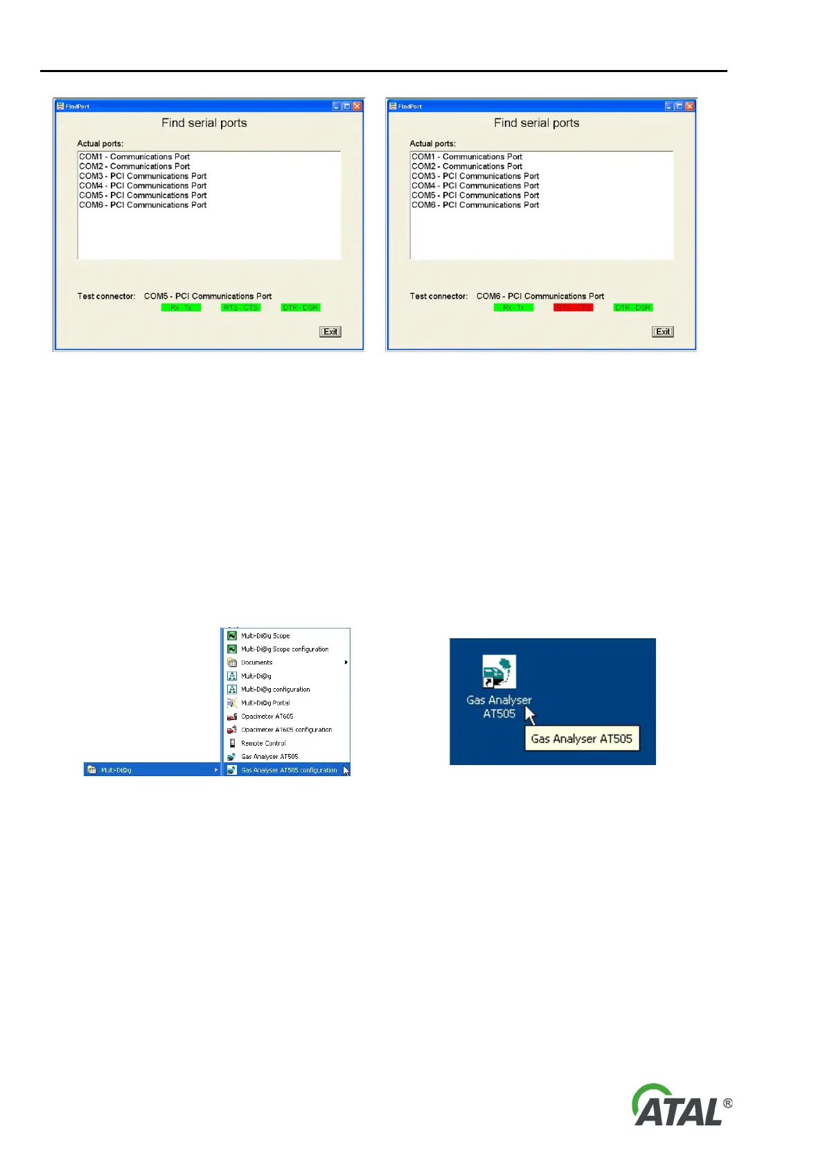
After successful program installation, a new Multi-Diag program group is created (see Fig. 34), or updated if it
already exists. A Gas analyser AT505 icon (see Fig. 35) is placed on the desktop.
Fig. 34 – Multi-Diag program group (Start \ Programs \ ... ) Fig. 35 – Gas Analyser program icon is placed on the desktop
9. DEVICE SWITCH-ON AND SOFTWARE START-UP
Before you start the software, the Gas Analyser should be connected to the power supply and computer and it
should be correctly configured. The Speed Sensor should also be connected to the computer and configured. If
there is a problem with communication to either of the devices, the software will notify the operator with a fault
message and it will not be able to carry out any test.