Chap. I - Gas Analyser
Gas-manual-en.docx — 22 —
10.2 GAS ANALYSER - IS NOT AVAILABLE MULTI-DIAG SCOPE
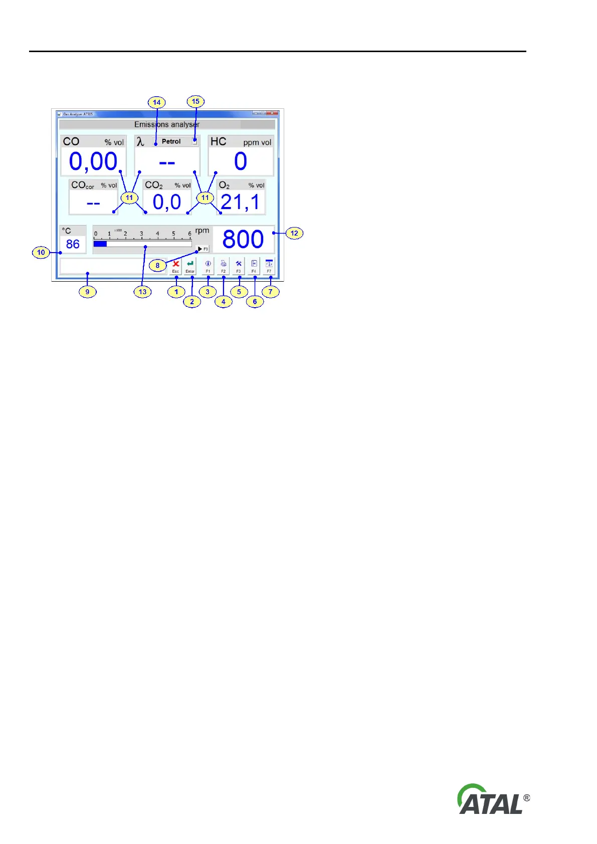
Fig. 45 – Initial Gas Analyser Software screen description (Multi-Diag Scope is not available)
Description of the Fig. 43 and Fig. 44:
1 - Button: Used to exit from the program
2 - Button: Green = measurement enabled
Red = standby, fault or initialisation - see the Note below
by pressing this button you will switch between standby and measuring mode
3 - Button: Display information about the program and connection (see Fig. 51)
4 - Button: Prints the currently displayed data
5 - Button: Configures several program parameters (see Fig. 46)
6 - Button: Used to start the emission test
7 - Button: Switches over to another application
8 - Button: Calibrate the Universal Speed Sensor. For information on how to read data using the vehicle ECU
9 - Screen: Displays information about program operation
10 - Screen: Displays the engine temperature
11 - Screen: Displays gas components
12 - Screen: Displays the engine speed
13 - Screen: Displays the engine speed graphically
14 - Screen: Selected fuel
15 - Quick option: fuel selection for lambda calculation (petrol, LPG, or CNG)
16 - Tab: Gas measuring (applies to Fig. 44)
Note to Button 2 - Fig. 45 (ENTER Button):
The ENTER button is used for switching to emergency mode, where the pump is turned off. The apparatus can
also move to emergency state also automatically. After transferring to the emergency state the apparatus always
carries out zeroing.
11. INITIAL ANALYSER SETUP
The analyser settings can be changed to configure it as required.
Here you can change the setting of the Speed and Temperature Sensor, fuel type and several other features of
the program. You can get to the setup mode by clicking on the button F3 (Pos.5 - Fig. 45).