Chap. I - Gas Analyser
Gas-manual-en.docx — 13 —
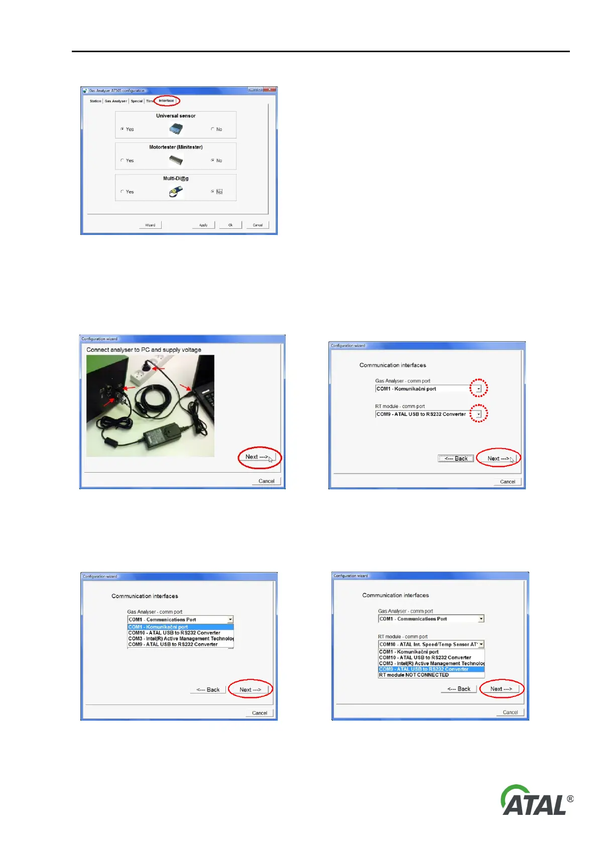
Fig. 20 – The configuration screen (Interface) - for enabling or
disabling the usage of peripheral equipment
8.1.6 PROGRAM CONFIGURATION WIZARD
The Wizard (see Fig. 16, pos. 11) starts automatically when the configuration utility is ran for the first time.
Fig. 21 – Connection of the Gas Analyser to the PC and to the power
supply
Fig. 22 – Communication ports setup for the Gas Analyser and the
Speed / Temperature Sensor module (performed by the user)
Note to Fig. 22:
When you click the arrow in "comm port", a list of available communication ports (see Fig. 23)
Fig. 23 – The list of available communication ports