Digital Life Controller Features and Operation
Digital Life User Manual | Page 4 of 62 ATT-UM-V1.1-201303
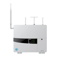
Digital Life Controller (DLC-100) Operation
The five (5) System LIGHTs on the DLC-100 door provide the following at-a-glance
status:
FEATURE OPERATION
AC POWER
• FLASHING GREEN LIGHT indicates your DLC is
powering up
• GREEN LIGHT indicates DLC is operational
• LIGHT OFF indicates LOCAL POWER FAILURE
NOTE: During LOCAL POWER FAILURE the BATTERY,
SYSTEM and WIRELESS BROADBAND lights will be
FLASHING GREEN. Wireline Broadband data will not be
operating.
BATTERY
• GREEN LIGHT indicates the battery is fully charged
• RED LIGHT indicates the battery needs to be replaced
• LIGHT OFF indicates the battery is dead or there is no
battery
SYSTEM
• GREEN LIGHT indicates your system is working
• RED LIGHT indicates your system has a problem
• YELLOW LIGHT indicates your system is in
Maintenance Mode
• YELLOW LIGHT FLASHING then GREEN LIGHT
FLASHING indicates Radio Frequency (RF) jamming is
being detected
Type of RF Jamming SYSTEM LIGHT Behavior
One-Way Jamming at
DLC-100 Digital Life
Controller Cabinet
SYSTEM LIGHT blinks yellow
once, blinks green once then
repeats
Two-Way Jamming at
DLC-100 Digital Life
Controller Cabinet
SYSTEM LIGHT blinks yellow
once, blinks green twice then
repeats
One-Way Jamming at a
Repeater
SYSTEM LIGHT blinks yellow
once, blinks green three (3)
times then repeats
Two-Way Jamming at a
Repeater
SYSTEM LIGHT blinks yellow
once, blinks green four (4)
times then repeats
 Loading...