Manual, Robotic Tool Changer, QC-5 through QC-27
Document #9610-20-2254-09
Pinnacle Park • 1041 Goodworth Drive • Apex, NC 27539 USA • Tel: 919.772.0115 • Fax: 919.772.8259 • www.ati-ia.com
14
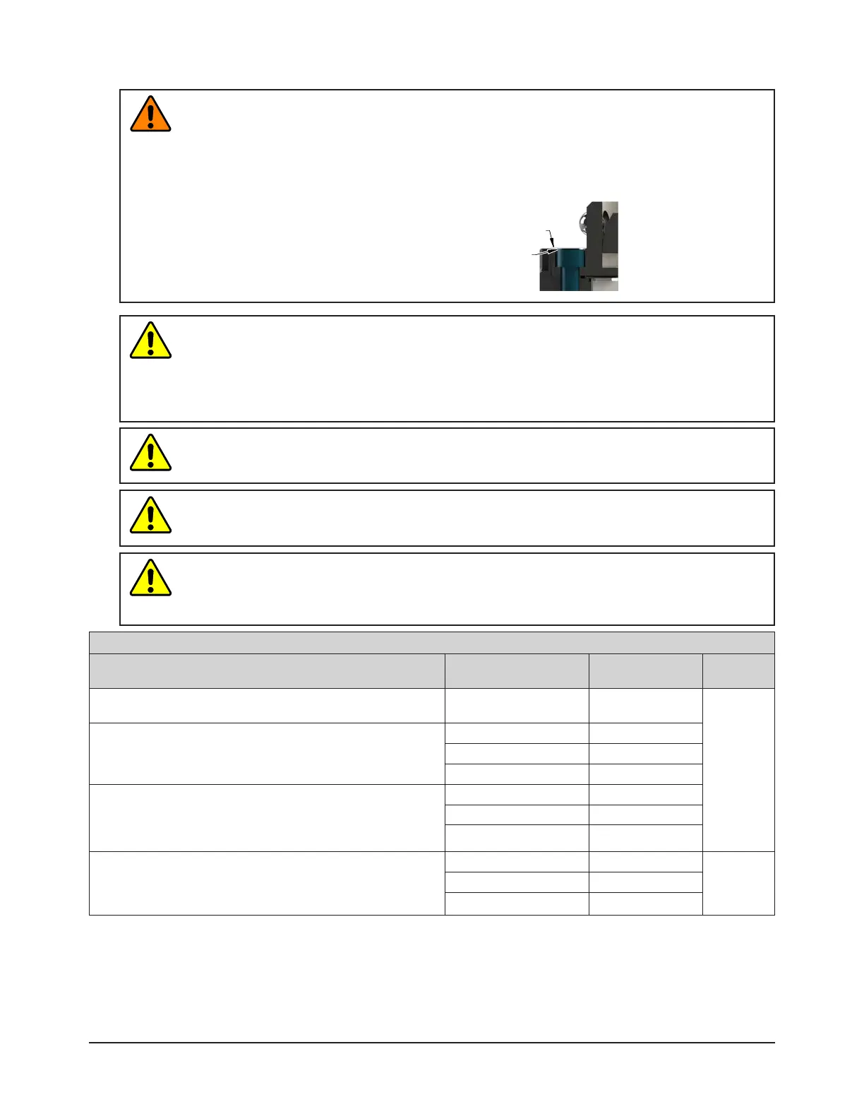
WARNING: Do not use lock washers under the head of the mounting fasteners or allow the
mounting fasteners to protrude above the mating surfaces of the Master and Tool plates.
Allowing fasteners to protrude above the mating surface will create a gap between the Master
and Tool plates and not allow the locking mechanism to fully engage, this can cause damage
to equipment or personal injury. The mounting fasteners must be ush or below the mating
surfaces of the Master and Tool plates.
Head of Mounting Fastener Must Be Flush or
Below Mating Surface. (Do Not Use Lock
Washer under Head of Mounting Fastener.)
Mating Surface
CAUTION: Do not apply Lock or Unlock air pressure to the Tool Changer prior to installing an
interface plate. Applying air pressure before the installation of an interface plate can damage
the cover plate, O-ring, or may cause injury to personnel from ying debris. Always install an
appropriate interface plate and mount the Tool Changer securely to the robot before applying
air pressure. Refer to Section 3.1—Robot Interface Plates and Section 3.2—Master Plate
Installation for more information.
CAUTION: Do not use fasteners with pre-applied adhesive more than once. Fasteners
might become loose and cause equipment damage. Always apply new thread locker when
reusing fasteners.
CAUTION: Do not use fasteners that exceed the thread depth in the Tool Changer’s robot or
tool side. Refer to Section 9—Drawings for details on the mounting hole thread depth. Secure
the Tool Changer with the proper length fasteners.
CAUTION: Failure to follow the interface plate design considerations in Section 3.1—Robot
Interface Plates and Section 3.4—Tool Interface Plate may result in damage to the cover plate
or O-ring or loose mounting between the interface plate and Tool Changer. Guidelines for the
interface plate design(s) should be followed.
Table 3.1—FastenerSize,Class,andTorqueSpecications
Mounting Conditions
Fastener Size, Property
Class, and type
Recommended
Torque
Thread
Locker
QC-5 and QC-11 Master plate to Robot Interface Plate or Sensor
Interface plate, Supplied Fasteners (M3 socket head cap screws)
M3-30
Class 12.9
10 in-lbs
(1.13 Nm)
Pre-applied
Adhesive
or Loctite
®
222
QC-20, QC-21, and QC-27 Master plate to Robot Interface Plate
or Sensor Interface plate, Supplied Fasteners
M4-30 Class 12.9
Socket at head cap 10 in-lbs (1.13 Nm)
Socket head cap 15 in-lbs (1.69 Nm)
Tool Interface Plate to QC-5 and QC-11 Tool plate
Minimum thread engagement of 7.5 mm [1.5X fastener Ø]. Do
not exceed maximum available thread depth of 8 mm as shown
in
Section 9—Drawings.
M5 x 0.8 Class 12.9
Socket head cap 45 in-lbs (5.08 Nm)
Socket at head cap 35 in-lbs (3.96 Nm)
Tool Interface Plate to QC-20, QC-21, and QC-27 Tool plate
Minimum thread engagement of 9 mm [1.5X fastener Ø]. Do not
exceed maximum available thread depth of 10 mm as shown in
Section 9—Drawings.
M6 x 1.0 Class 12.9
Pre-applied
Adhesive or
Loctite 242
Socket head cap 90 in-lbs (10.2 Nm)
Socket at head cap 60 in-lbs (6.78 Nm)