Manual, Robotic Tool Changer, QC-5 through QC-27
Document #9610-20-2254-09
Pinnacle Park • 1041 Goodworth Drive • Apex, NC 27539 USA • Tel: 919.772.0115 • Fax: 919.772.8259 • www.ati-ia.com
26
3.7.10 QC-21 Flat B Optional Module Removal
Tools required: 2.5 mm and 3 mm hex key
1. Place the Tool in a secure location.
2. Uncouple the Master and Tool plates.
3. Turn off and de-energize all energized circuits (e.g. electrical, air, water, etc.).
4. Disconnect the utility cable(s).
5. Remove the (4) M4 socket head cap screws using a 3 mm hex key.
6. Remove the module from the adapter plate.
7. Remove the (2) M4 socket at head cap screws securing the adapter plate to the Master or Tool
plate using a 2.5 mm hex key.
8. Remove the adapter plate.
3.8 Installing an Optional SIP
The optional SIP is typically installed on Tool Changers by ATI prior to shipment. The following steps
outline eld installation. The SIP typically includes a custom interface plate that may replace the existing
interface plate. For interface plate installation, refer to Section 3.2—Master Plate Installation.
The SIP assembly comes partially assembled, the Lock and Unlock sensors are assembled to the proper
position in the sensor plate. Do not remove the sensors or adjust the position. The small detection shaft’s
O-ring is lubricated and installed in the sensor plate.
3.8.1 QC-11 SIP Assembly Installation
Tools required: 2.5 mm and 3 mm hex key, torque wrench
Parts required: 9120-011M-SIP-xxxx (where xxxx is the custom SIP interface plate)
Supplies required: Magnalube (if necessary)
1. Place the Tool in a secure location.
2. Uncouple the Master and Tool plates.
3. Turn off and de-energize all energized circuits (e.g. electrical, air, water, etc.).
4. Remove the Tool Changer Master plate from the robot and the interface plate, refer to
Section 3.3—Master Plate Removal.
5. If the Tool Changer has a cover plate, remove the cover plate from the robot side of
the Tool Changer.
6. Make sure the O-ring in the Master plate is present and in good condition, lubricate with
Magnalube if needed.
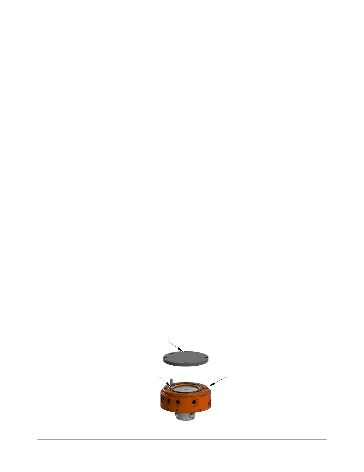
Figure 3.9—QC-11 Cover Plate Removal
O-ring
Tool Changer
Master Plate