Manual, Robotic Tool Changer, QC-5 through QC-27
Document #9610-20-2254-09
Pinnacle Park • 1041 Goodworth Drive • Apex, NC 27539 USA • Tel: 919.772.0115 • Fax: 919.772.8259 • www.ati-ia.com
16
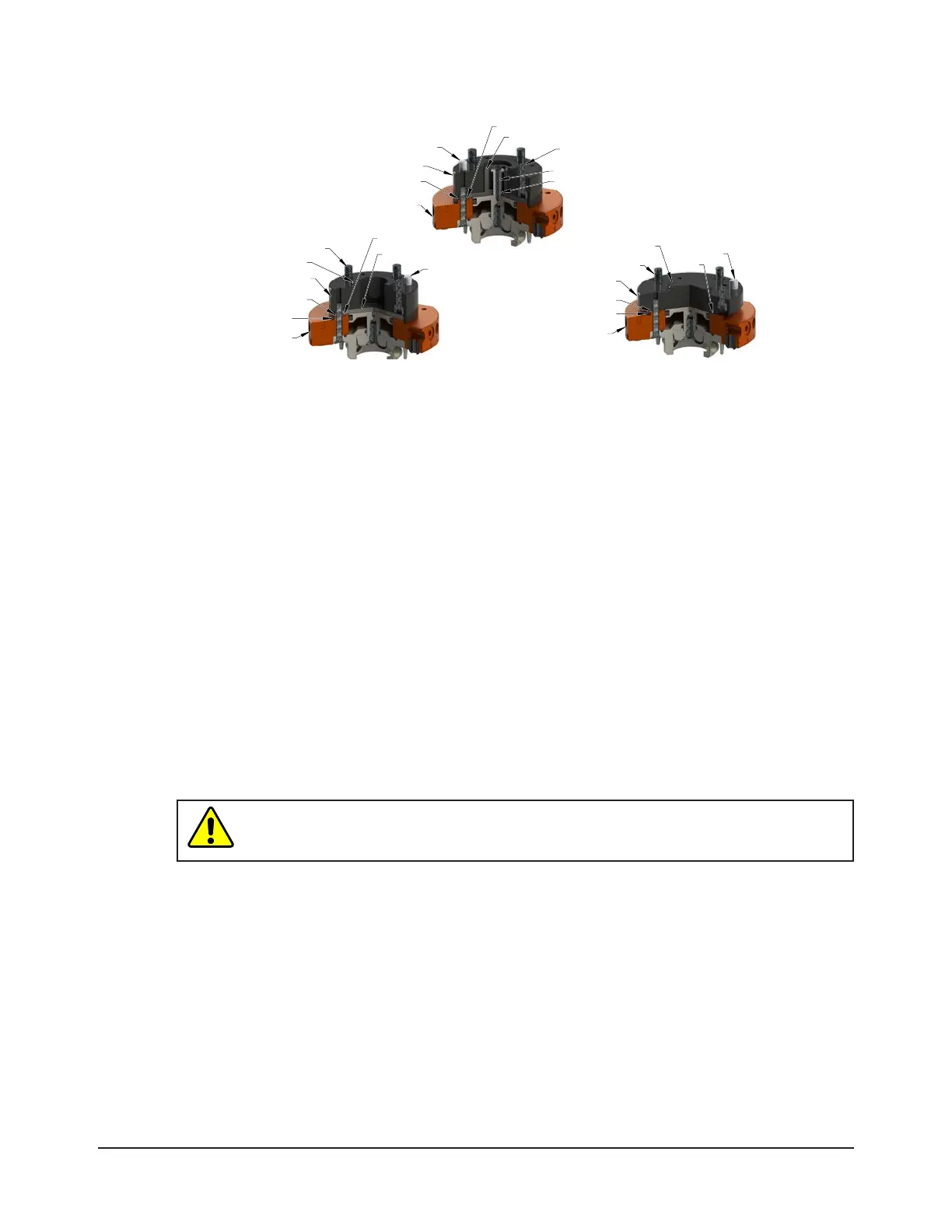
Figure 3.1—CongurationsforaMasterwithanInterfacePlate
Sensor Interface Plate (SIP)
Master Plate Body
Master Plate Boss
Sensor Plate (Cover Plate Removed)
Detection shaft
O-ring
Dowel Pin
Mounting Fasteners
(Supplied by Customer)
Interface Plate
Master Plate Body
Master Plate Boss
O-ring
Maintain a Gap
Boss
Dowel Pin
Mounting Fasteners
(Supplied by Customer)
Cover Plate Removed
Interface Plate
Master Plate Boss
Master Plate Body
Maintain a Gap
Cover Plate Left in Place
O-ring
Dowel Pin
Boss
Mounting Fasteners
(Supplied by Customer)
3.2 Master Plate Installation
The Tool Changer Master plate mounts to the robot ange using an interface plate. A cover plate that
attaches to the Master plate protects the internal locking mechanism during shipment. Depending on
the Master and interface plate conguration, remove the cover plate or install an interface plate to
the cover plate.
Refer to
Figure 3.2
Tools required: 2 mm, 2.5 mm, and/or 3 mm hex key wrench(es), torque wrench
Supplies required: Clean rag, Loctite
®
222
1. Clean the mounting surfaces.
2. Position the interface plate to the robot arm and secure with the supplied or customer supplied fasteners,
refer to Figure 3.2. Refer to Table 3.1 for proper fasteners and torque.
3. Determine the Master and interface plate conguration:
• The interface plate replaces the cover plate. Go to step 4.
• The interface plate incorporates the cover plate. Go to step 5.
4. Remove the cover plate.
• For the QC-5 or QC-11, remove the (2) M3 hex nuts securing the cover plate to the Master plate.
• For a QC-20 and QC-21, remove the (2) M3 socket at head screws using a 2 mm hex key that secure
the cover plate to the Master plate.
CAUTION: Make sure the O-ring is properly seated in the Master plate’s groove, or the
seal could leak because of a cut or damage from improper installation. Properly seat
O-ring into groove in Master plate.