Manual, Robotic Tool Changer, QC-5 through QC-27
Document #9610-20-2254-09
Pinnacle Park • 1041 Goodworth Drive • Apex, NC 27539 USA • Tel: 919.772.0115 • Fax: 919.772.8259 • www.ati-ia.com
24
3.7.7 QC-20, QC-21, and QC-27 Flat A Optional K Series Module Installation
Tools required: 2.5 mm hex key, torque wrench
Supplies required: Clean rag, Loctite 222
1. Place the Tool in a secure location.
2. Uncouple the Master and Tool plates.
3. Turn off and de-energize all energized circuits (e.g. electrical, air, water, etc.).
4. Ensure that the mounting surface is clean.
5. Align the optional module on at A of Master or Tool plate assembly.
6. Apply Loctite 222 to the M3 socket head cap screws.
7. Secure the module with (2) M3 socket head cap screws using a 2.5 mm hex key. Tighten to
10 in-lbs (1.13 Nm).
8. Remove all protective caps, plugs, tape, etc from the module prior to operation.
9. Connect the utility cable(s).
10. Safely resume normal operation.
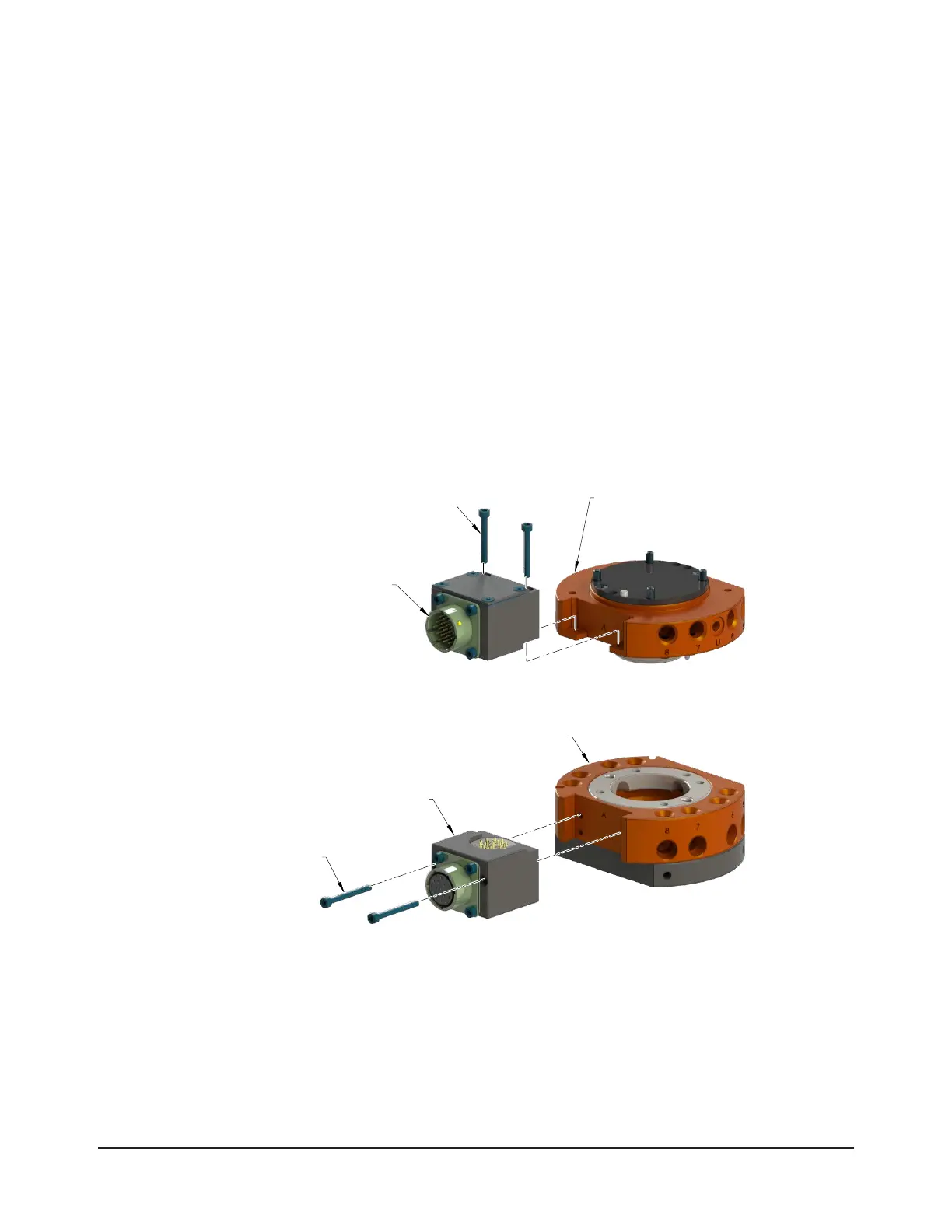
Figure 3.7—QC-20 and QC-21 Flat A Optional K Series Module Installation
Electric Module
(9120-K19-T)
Tool Plate Assembly
(QC-21 Shown)
(QC-21 Shown)
(2) M3 Socket Head
Cap Screw
Electrical Module
(9120-K19-M Shown)
(2) M3 Socket Head
Cap Screw
3.7.8 QC-20, QC-21, and QC-27 Flat A Optional K Series Module Removal
Tools required: 2.5 mm hex key
1. Place the Tool in a secure location.
2. Uncouple the Master and Tool plates.
3. Turn off and de-energize all energized circuits (e.g. electrical, air, water, etc.).
4. Disconnect the utility cable(s).