Manual, Robotic Tool Changer, QC-5 through QC-27
Document #9610-20-2254-09
Pinnacle Park • 1041 Goodworth Drive • Apex, NC 27539 USA • Tel: 919.772.0115 • Fax: 919.772.8259 • www.ati-ia.com
64
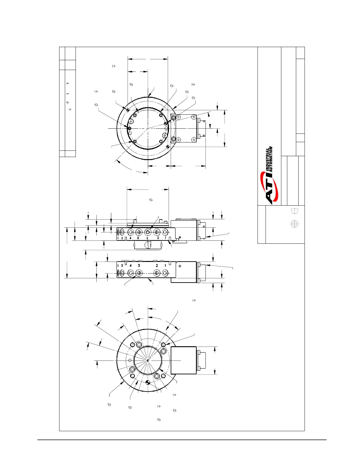
9.3 QC-20 Tool Changer with K19 Module
3rd ANGLE PROJECTION
90
39.8
K19
Modules
40 H7
6
Customer Interface
6 H7
10
Customer Interface
B.C.
63
17°
(Typ.)
17°
(Typ.)
17°
(Typ.)
17°
(Typ.)
45°
4X Tapped M6x1
10
Equally Spaced
Customer Interface
1
2
3
4
5
6
7
8
9
10
11
12
Tool Side
(projection only)
Pneumatic
Port I.D.
23.7
Tool
Plate
30.6
K19-M
12
3
Boss
Coupled
42.4
60
h7, Boss
Customer
Interface
18.7
Master
Plate
13.5
Male
Coupling
30.6
K19-T
6.9
9 M4 SFHCS
Provided
3.2
Cover
Plate
16.7
12
M5
Lock
Port
Amphenol Connector
PT02E-14-19P
Amphenol Connector
PT02E-14-19S
(A)
(B)
12X M5
Pneumatic
Thru Ports
12X M5
Pneumatic
Thru Ports
50
K19
Modules
33
(Typ.)
90
28.8
57.5
26.3
52.7
58.4
Cover
Plate
4 H7
7
Customer Interface
4 H7
7
Customer Interface
2X
4 SF Dowel
6
Customer Interface
B.C.
53
15°
45°
4X Thru Hole for M4x30
SFHCS Provided
Equally Spaced
Customer Interface
M5
Unlock
Port
Master Side
(projection only)
Notes:
1. Master mounting hardware provided.
2. Cover plate is not necessary if robot interface plate provides
sealing. The recommended interface plate bore depth without
a cover plate is 2.5mm, with a cover plate is 5.6mm.
3. Orientation marks are provided to assist in robot teaching.
4. Shown with optional K19 Electrical Modules. For other modules
see the Modules and Options section of the catalog.
Part Numbers Shown:
(A) Master: 9120-020M-K19-PM5
(B) Tool: 9120-020T-K19-PM5
Warning:
Do not apply lock/unlock air pressure without master cover plate
properly attached. If cover plate is not used, master should be
properly attached to interface. Failure to do so could result in
damage to cover plate and o-ring.
Rev.
Description
Initiator
Date
04
ECO 14321; Master Side - 2 locations
4 H7
7 was
4 (dowel
hole farthest from module) and
14 (dowel hole closest to
module). Updated Title Block and filled in "Checked By:" field
SZJ
4/26/2016
B
1:1.3
1 1
REVISION
NOTES: UNLESS OTHERWISE
SPECIFIED.
DO NOT SCALE DRAWING.
ALL DIMENSIONS ARE IN
MILLIMETERS.
DRAWN BY:
CHECKED BY:
P.Sparrow, 7/22/04
D. Wagner, 5/2/16
TITLE
SCALE
SIZE
DRAWING NUMBER
PROJECT #
SHEET OF
9230-20-1964
04
PROPERTY OF ATI INDUSTRIAL AUTOMATION, INC. NOT TO BE REPRODUCED IN ANY
MANNER EXCEPT ON ORDER OR WITH PRIOR WRITTEN AUTHORIZATION OF ATI.
1031 Goodworth Drive, Apex, NC 27539, USA
Tel: +1.919.772.0115 Email: info@ati-ia.com
Fax: +1.919.772.8259 www.ati-ia.com
ISO 9001 Registered Company
QC-20 Tool Changer