Manual, Robotic Tool Changer, QC-5 through QC-27
Document #9610-20-2254-09
Pinnacle Park • 1041 Goodworth Drive • Apex, NC 27539 USA • Tel: 919.772.0115 • Fax: 919.772.8259 • www.ati-ia.com
36
4. Operation
The Master locking mechanism is pneumatically driven to couple and uncouple with the bearing race on the Tool
plate. The Master plate utilizes air ports to provide lock and unlock pressure to the locking mechanism.
CAUTION: Safe, reliable operation of the Tool Changer is dependent on a continuous supply
of compressed air at a pressure of 60 to 100 psi (4.1 - 6.9 Bar). Robot motion should be
halted if the air supply pressure drops below 60 psi (4.1 Bar) for any reason.
NOTICE: All standard Tool Changers are initially lubricated using MobilGrease® XHP222 Special
grease. The end user must apply additional lubricant to the locking mechanism components and
alignment pins prior to start of service (See Section 5.2—Cleaning and Lubrication of the Locking
Mechanism and Alignment Pins). Tubes of lubricant for this purpose are shipped with every Tool
Changer. Note: MobilGrease XHP222 Special is a NLGI #2 lithium complex grease with molybdenum
disulde. For custom Tool Changers lubricant may vary, contact an ATI Sales Representative for
specic requirements for custom applications.
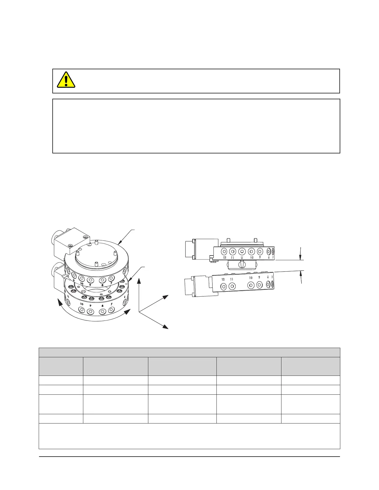
The robot should be programmed to minimize misalignment during coupling and uncoupling. Additionally, the tool
stand should be durable and not allow deection, under uncoupled Tool weight that will take alignment of the Tool
Changer plates outside of accepted offsets. See Figure 4.1 and Table 4.1 for recommended maximum allowable
offsets prior to coupling. In some cases, greater offsets than shown in Table 4.1 can be accommodated by the
Master and Tool plates but will increase wear.
Lock-up should occur with the Master plate in the No-Touch™ locking zone (see Table 4.1) but not touching the
Tool plate. As locking occurs, the Master plate should draw the Tool plate into the locked position.
Figure 4.1—OffsetDenitions
Master Plate
Tool Plate
Cocking Offset
(About X and Y)
Twisting Offset
(About Z)
Z
Y
X
X, Y, and Z Offset
Table 4.1—Maximum Recommended Offsets Prior to Coupling
Model
No-Touch™ Zone Z
Offset (Max)
1
X and Y Offset (Max)
2
Cocking Offset
(Max) (degrees)
Twisting Offset
(Max) (degrees)
QC-5 2 mm (0.08”) ±1 mm (0.039”) ±1.1 ±2
QC-11 1.5 mm (0.06”) ±1 mm (0.039”) ±0.8 ±2
QC-20
QC-21
2 mm (0.08”) ±1 mm (0.039”) ±0.8 ±2
QC-27
3 mm (0.12”) ±2 mm (0.08”) ±1.0 ±2
Notes:
1. Maximum values shown. Decreasing the actual values minimize wear during coupling and uncoupling.
2. Actual allowable values may be higher in some cases, but higher offsets increase wear during coupling.