Manual, Robotic Tool Changer, QC-5 through QC-27
Document #9610-20-2254-09
Pinnacle Park • 1041 Goodworth Drive • Apex, NC 27539 USA • Tel: 919.772.0115 • Fax: 919.772.8259 • www.ati-ia.com
21
3.7 Optional Module Installation
Tool Changers are compatible with many different types of modules. Some modules require an adapter plate
to be installed to the Tool Changer. The optional modules are typically installed on Tool Changers by ATI
prior to shipment. The following steps outline eld installation or removal.
3.7.1 QC-5 and QC-11 Simple Electrical Module Installation
Tools required: 2.5 mm hex key, torque wrench
Supplies required: Clean rag, Loctite 222
1. Place the Tool in a secure location.
2. Uncouple the Master and Tool plates.
3. Turn off and de-energize all energized circuits (e.g. electrical, air, water, etc.).
4. Make all soldered connections to the simple electrical module as desired.
5. Clean the mounting surfaces.
6. Align the module to the at of the Master or Tool plate assembly.
7. Apply Loctite 222 to M3 socket head cap screws.
8. Secure the module with (2) M3 socket head cap screws using a 2.5 mm hex key. Tighten to
24 in-oz (0.17 Nm).
9. Remove all protective caps, plugs, tape, etc from the module prior to operation.
10. Connect the utility cable(s).
11. Safely resume normal operation.
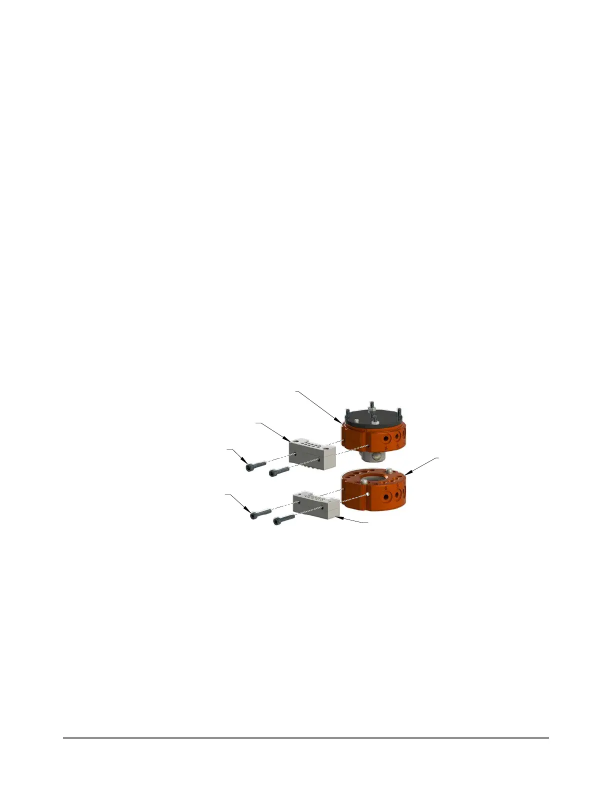
Figure 3.4—QC-11 Simple Electrical Module Installation
(2) M3 Socket Head Cap Screws
Tool Plate Assembly
(QC-11 Shown)
(QC-11 Shown)
(2) M3 Socket Head Cap Screws
Electrical Module
(9120-E10M-010 Shown)
Electrical Module
3.7.2 QC-5 and QC-11 Simple Electrical Module Removal
Tools required: 2.5 mm hex key
1. Place the Tool in a secure location.
2. Uncouple the Master and Tool plates.
3. Turn off and de-energize all energized circuits (e.g. electrical, air, water, etc.)
4. Disconnect the utility cable(s).
5. Remove the (2) M3 socket head cap screws using a 2.5 mm hex key.
6. Remove the module from the Master or Tool plate.