Manual, Robotic Tool Changer, QC-5 through QC-27
Document #9610-20-2254-09
Pinnacle Park • 1041 Goodworth Drive • Apex, NC 27539 USA • Tel: 919.772.0115 • Fax: 919.772.8259 • www.ati-ia.com
63
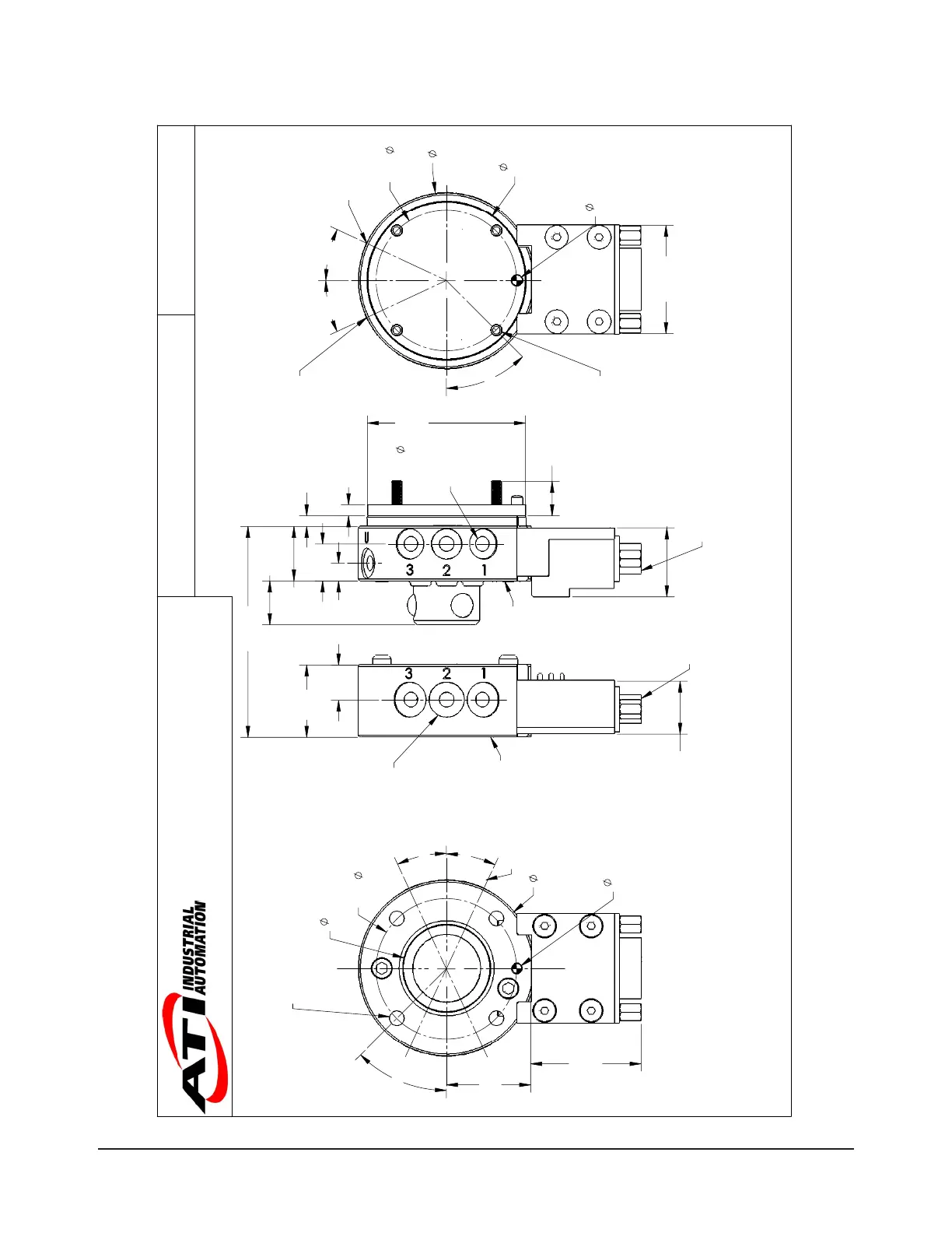
9.2 QC-11 Tool Changer with A15 Module
25
H8, 5 Dp.
Customer Interface
3
H7, 5 Dp.
Customer Interface
50
24
(Typ.)
31.5
A15
Modules
B.C.
40
45°
25°
25°
4X Tapped M5 x .8, 8 Dp.
Equally Spaced
Customer Interface
2
3
6
5
4
Tool Side
(projection only)
Pneumatic
Port I.D.
1
20.6
Tool
Plate
12.5
Male
Coupling
3.2
Cover Plate
Coupled
36.1
15.1
A15-T
19.6
A15-M
45
h7, Boss
Customer
Interface
15.5
Master
Plate
9.8 M3 SHCS
Provided
3 Boss
10 5
10.5
6X M5
Pneumatic
Thru Ports
(A)
(B)
HD D-Sub 15
Female Connector
HD D-Sub 15
Male Connector
6X M5
Pneumatic
Thru Ports
44.7
Cover
Plate
3
H7, 5 Dp.
Customer Interface
30.8
A15
Modules
50
B.C.
40
25° 25°
45°
4X Thru Hole for M3 x 25
SHCS Provided
Equally Spaced
Customer Interface
M5 Unlock
Port
M5 Lock
Port
Master Side
(projection only)
Part Numbers Shown:
(A) Master: 9120-011M-A15-000
(B) Tool: 9120-011T-A15-000
Notes:
1. Master mounting hardware provided.
2. Cover plate is not necessary if robot interface plate provides
sealing. The recommended interface plate bore depth without
a cover plate is 2.5mm, with a cover plate is 5.6mm.
3. Orientation marks are provided to assist in robot teaching.
4. Shown with optional A15 Electrical Modules. For other modules
see the Modules and Options section of the catalog.
Warning:
Do not apply lock/unlock air pressure without master cover plate
properly attached. If cover plate is not used, master should be
properly attached to interface. Failure to do so could result in
damage to cover plate and o-ring.
QC-11 Tool Changer
9230-20-1963-05
1031 Goodworth Drive, Apex, NC 27539, USA
Tel: +1.919.772.0115 Email: info@ati-ia.com
Fax: +1.919.772.8259 www.ati-ia.com
ISO 9001 Registered Company