Manual, Robotic Tool Changer, QC-5 through QC-27
Document #9610-20-2254-09
Pinnacle Park • 1041 Goodworth Drive • Apex, NC 27539 USA • Tel: 919.772.0115 • Fax: 919.772.8259 • www.ati-ia.com
13
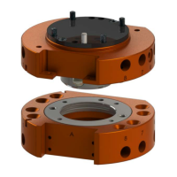
2.5 Optional Modules
Tool Changers have (1) or (2) ats depending on the model. Optional modules support the pass-through
of various utilities, such as signal, uid/air, and power, etc. Refer to Table 2.2 for more information. Some
modules require an adapter plate.
For assistance in choosing the right modules for your particular application, visit the ATI website or contact
an ATI Sales Representative.
Table 2.2—Tool Changer Models and Features
Model
Forthemostcurrentlist,information,andspecicationsforcompatible
Optional Modules click the link below
QC-5 QC-5 Web Page and select the Compatible modules tab
QC-11 QC-11 Web Page and select the Compatible modules tab
QC-20 QC-20 Web Page and select the Compatible modules tab
QC-21 QC-21 Web Page and select the Compatible modules tab
QC-27 QC-27 Web Page and select the Compatible modules tab
Note: The ATI website provides information on the standard compatible modules additional custom
modules are available, contact an ATI Sales Representative.
3. Installation
The Master plate of the Tool Changer mounts to the robot arm using an interface plate. Custom interface plates are
available from ATI upon request. Refer to Section 3.1—Robot Interface Plates or Section 2.4—Optional Sensor
Interface Plate (SIP) for more information.
The end-effector is typically attached to the Tool plate with an interface plate,standard and custom tool interface
plates are available from ATI upon request. Refer to Section 3.4—Tool Interface Plate for more information.
All fasteners used to mount the Tool Changer to the robot and to customer’s tooling should have pre-applied
adhesive or be applied with removable (blue) Loctite and tightened to a torque value as indicated in Table 3.1,
which contains recommended torque values based on engineering standards. Because custom Tool Changers may
use different mounting fasteners, the specications for torque and thread locker may vary; contact an ATI sales
representative for more information.
Pneumatic lines and electrical cables are attached, bundled, and must be strain-relieved in a manner that allows for
freedom of movement during operation.
WARNING: Do not perform maintenance or repair on Tool Changer or modules unless the
Tool is safely supported or placed in the tool stand, all energized circuits (e.g. electrical,
air, water, etc.) are turned off, pressurized connections purged and power discharged from
circuits in accordance with the customer’s safety practices and policies. Injury or equipment
damage can occur with Tool not placed and energized circuits on. Place the Tool safely in the
tool stand, turn off and discharge all energized circuits, purge all pressurized connections,
verify all energized circuits are de-energized before performing maintenance or repair on Tool
Changer or modules.
WARNING: All pneumatic ttings and tubing must be capable of withstanding the repetitive
motions of the application without failing. The routing of electrical and pneumatic lines must
minimize the possibility of over stressing, pullout, or kinking the lines. Failure to do so can
cause some critical electrical and/or pneumatic lines not to function properly and may result in
injury to personnel or damage to equipment.