Manual, Robotic Tool Changer, QC-5 through QC-27
Document #9610-20-2254-09
Pinnacle Park • 1041 Goodworth Drive • Apex, NC 27539 USA • Tel: 919.772.0115 • Fax: 919.772.8259 • www.ati-ia.com
22
3.7.3 QC-5 and QC-11 Master Electrical Module Installation
Tools required: 2.5 mm and 2 mm hex key, torque wrench
Supplies required: Clean rag, Loctite 222
1. Place the Tool in a secure location.
2. Uncouple the Master and Tool plates.
3. Turn off and de-energize all energized circuits (e.g. electrical, air, water, etc.).
4. Clean the mounting surfaces.
5. Remove the (4) M3 socket head cap screws that secure the cover to the module using
a 2 mm hex key.
6. Align the cover to the Master plate.
7. Apply Loctite 222 to the M3 socket head cap screws.
8. Secure the cover with (2) M3 socket head cap screws using a 2.5 mm hex key. Tighten to
48 in-oz (0.34 Nm).
9. Apply Loctite 222 to the (4) M3 socket at head cap screws.
10. Attach the module to the cover using the (2) long and (2) short M3 socket at head cap screws
using a 2.5 mm hex key. Tighten to 48 in-oz (0.34 Nm).
11. Remove all protective caps, plugs, tape, etc from the module prior to operation.
12. Connect the utility cable(s).
13. Safely resume normal operation.
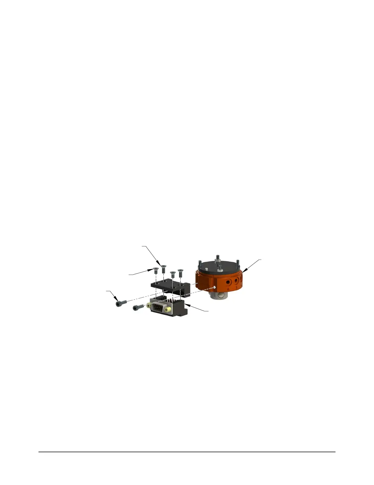
Figure 3.5—QC-11 Master Electrical Module Installation
(2) M3 Socket Head
Cap Screws
Master Plate Assembly
(QC-11 Shown)
(2) M3 Socket Flat Head
Cap Screws (Long)
Electrical Module
(9120-A15-M Shown)
(2) M3 Socket Flat Head
Cap Screws (Short)
3.7.4 QC-5 and QC-11 Master Electrical Module Removal
Tools required: 2.5 mm and 2 mm hex key
1. Place the Tool in a secure location.
2. Uncouple the Master and Tool plates.
3. Turn off and de-energize all energized circuits (e.g. electrical, air, water, etc.).
4. Disconnect the utility cable(s).
5. Remove the (4) M3 socket at head cap screws holding the module to the cover using a
2.5 mm hex key.
6. Remove the module from the cover.
7. Support the cover, while removing the (2) M3 socket head cap screws using a 2.5 mm hex key.
8. Remove the cover from the Master plate.