Manual, Robotic Tool Changer, QC-5 through QC-27
Document #9610-20-2254-09
Pinnacle Park • 1041 Goodworth Drive • Apex, NC 27539 USA • Tel: 919.772.0115 • Fax: 919.772.8259 • www.ati-ia.com
53
6.2.4 QC-27M Alignment Pin Replacement
Excessive alignment pin/bushing wear could indicate poor robot positioning during pickup/drop-
off. Adjust the robot position as needed. Check the tool stand for wear and alignment problems. If
necessary, replace the alignment pins.
Tools required: 2.5 mm hex key, torque wrench
Parts required: Refer to Section 8.6—Models QC-27 Serviceable Parts.
Supplies required: Loctite 242, MobilGrease XHP222 Special is a NLGI #2 lithium complex grease
with molybdenum disulde
1. Place the Tool in a secure location.
2. Uncouple the Master and Tool plates.
3. Turn off and de-energize all energized circuits (e.g. electrical, air, water, etc.).
4. Using a 2.5 mm hex key, remove the alignment pin and discard.
5. Apply Loctite 242 to the threads of the new alignment pin and thread into the Master plate
assembly. Tighten to 18 in-lbs (2.0 Nm).
6. Apply a liberal coating of MobilGrease XHP222 Special grease to the alignment pins.
7. Safely resume normal operation.
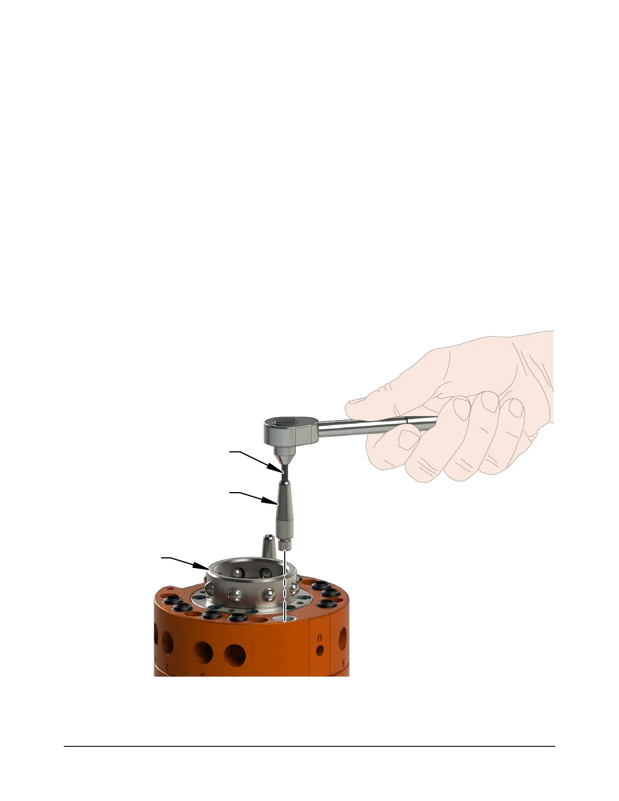
Figure 6.8—QC-27M Alignment Pin Replacement
2.5 mm Hex Key
Alignment Pin
QC-27 Master
Plate Assembly