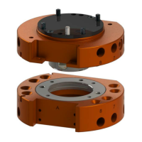
Manual, Robotic Tool Changer, QC-5 through QC-27
Document #9610-20-2254-09
Pinnacle Park • 1041 Goodworth Drive • Apex, NC 27539 USA • Tel: 919.772.0115 • Fax: 919.772.8259 • www.ati-ia.com
3
Table of Contents
Foreword .......................................................................................................................................... 2
1. Safety ......................................................................................................................................... 7
1.1 ExplanationofNotications .........................................................................................................7
1.2 General Safety Guidelines ............................................................................................................7
1.3 Safety Precautions ........................................................................................................................8
2. Product Overview ..................................................................................................................... 9
2.1 Master Plate Assembly ............................................................................................................... 11
2.2 Tool Plate Assembly .................................................................................................................... 11
2.3 Master Plate/Tool Plate Locking Mechanism ............................................................................ 12
2.4 Optional Sensor Interface Plate (SIP) ........................................................................................12
2.5 Optional Modules ........................................................................................................................13
3. Installation .............................................................................................................................. 13
3.1 Robot Interface Plates ................................................................................................................15
3.2 Master Plate Installation .............................................................................................................16
3.3 Master Plate Removal .................................................................................................................18
3.4 Tool Interface Plate .....................................................................................................................19
3.5 Tool Plate Installation .................................................................................................................20
3.6 Tool Plate Removal .....................................................................................................................20
3.7 Optional Module Installation ......................................................................................................21
3.7.1 QC-5 and QC-11 Simple Electrical Module Installation .................................................... 21
3.7.2 QC-5 and QC-11 Simple Electrical Module Removal ....................................................... 21
3.7.3 QC-5 and QC-11 Master Electrical Module Installation .................................................... 22
3.7.4 QC-5 and QC-11 Master Electrical Module Removal ....................................................... 22
3.7.5 QC-5 and QC-11 Tool Electrical Module Installation ........................................................ 23
3.7.6 QC-5 and QC-11 Tool Electrical Module Removal ........................................................... 23
3.7.7 QC-20, QC-21, and QC-27 Flat A Optional K Series Module Installation .........................24
3.7.8 QC-20, QC-21, and QC-27 Flat A Optional K Series Module Removal ............................24
3.7.9 QC-21 Flat B Optional Module Installation .......................................................................25
3.7.10 QC-21 Flat B Optional Module Removal ..........................................................................26
3.8 Installing an Optional SIP ........................................................................................................... 26
3.8.1 QC-11 SIP Assembly Installation ......................................................................................26
3.8.2 QC-20 and QC-21 SIP Assembly Installation ................................................................... 29
3.9 Lock and Unlock Pneumatic and Valve Requirements ............................................................33
3.10 Electrical Connections ................................................................................................................34
3.10.1 PNP Type Lock and Unlock Sensors ................................................................................34
3.10.2 NPN Type Lock and Unlock Sensors ............................................................................... 35

 Loading...