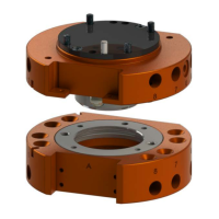
Manual, Robotic Tool Changer, QC-5 through QC-27
Document #9610-20-2254-09
Pinnacle Park • 1041 Goodworth Drive • Apex, NC 27539 USA • Tel: 919.772.0115 • Fax: 919.772.8259 • www.ati-ia.com
48
CAUTION: Be careful not to over tighten set screw. Over tightening set screw
can cause damage to the proximity sensor. Tighten until the nylon tip engages
with the sensor threads and tighten 1/4 turn more.
12. Attach the Master plate to the interface plate:
• For a QC-11 secure the Master plate to the interface plate using the (4) M3 socket head cap
screws using a 2.5 mm hex key. Tighten to 10 in-lbs (1.13 Nm).
• For a QC-27 secure the Master plate to the interface plate using the (6) M4 socket head cap
screws using a 3 mm hex key. Tighten to 15 in-lbs (1.68 Nm).
13. Connect other utilities to the optional modules on the Master plate.
14. Conrm the operation of the replaced sensor.
a. Provide Lock or Unlock air to the Tool Changer.
b. Verify the corresponding sensor signal is ON and the sensor LED is illuminated.
15. Safely resume normal operation.

 Loading...