115
8126F–AVR–05/12
ATtiny13A
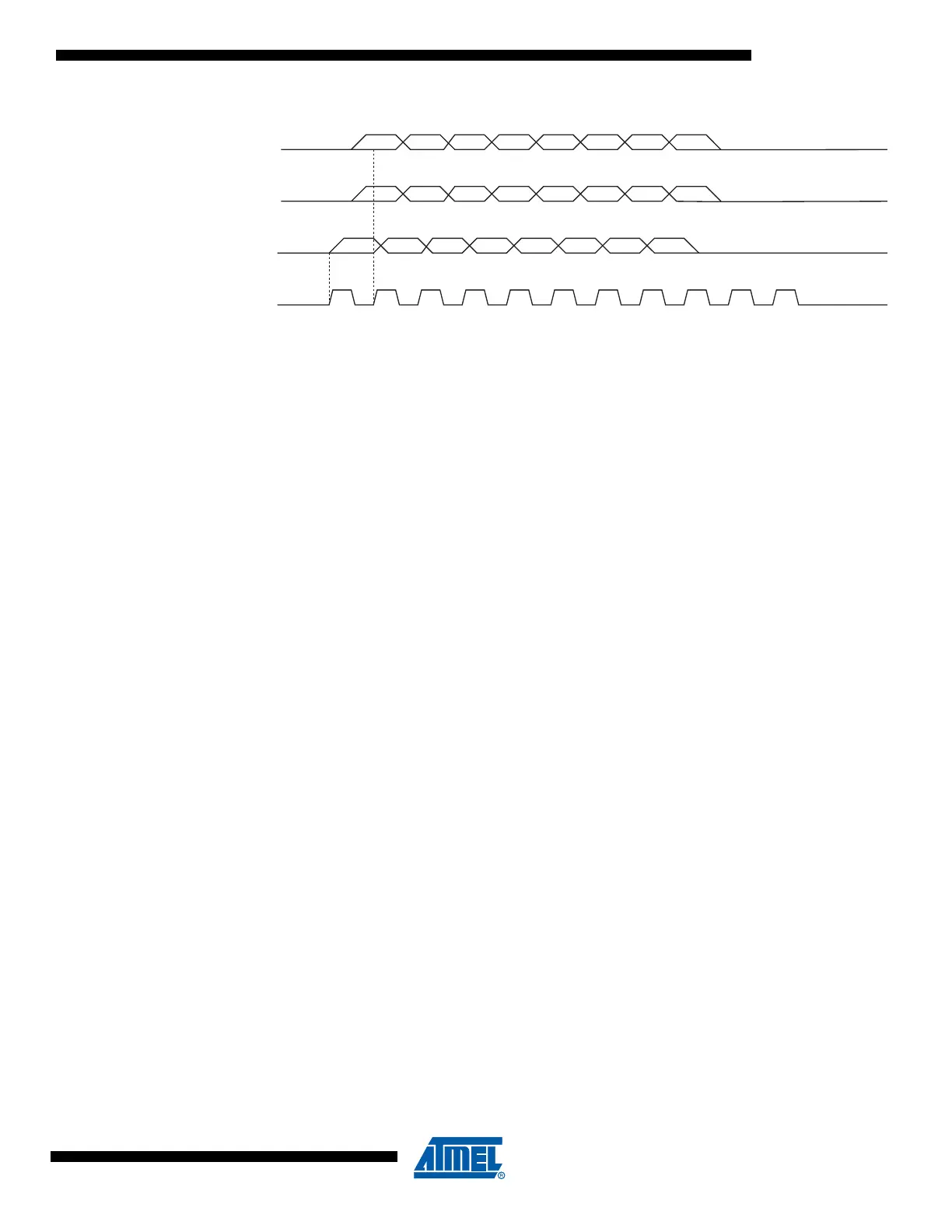
Figure 17-4. High-voltage Serial Programming Waveforms
17.8.3 Programming the EEPROM
The EEPROM is organized in pages, see Table 18-9 on page 122. When programming the
EEPROM, the data is latched into a page buffer. This allows one page of data to be pro-
grammed simultaneously. The programming algorithm for the EEPROM Data memory is as
follows (refer to Table 17-13 on page 111):
1. Load Command “Write EEPROM”.
2. Load EEPROM Page Buffer.
3. Program EEPROM Page. Wait after Instr. 2 until SDO goes high for the “Page Pro-
gramming” cycle to finish.
4. Repeat 2 through 3 until the entire EEPROM is programmed or until all data has been
programmed.
5. End Page Programming by Loading Command “No Operation”.
17.8.4 Reading the Flash
The algorithm for reading the Flash memory is as follows (refer to Table 17-13 on page 111):
1. Load Command "Read Flash".
2. Read Flash Low and High Bytes. The contents at the selected address are available at
serial output SDO.
17.8.5 Reading the EEPROM
The algorithm for reading the EEPROM memory is as follows (refer to Table 17-13 on page
111):
1. Load Command “Read EEPROM”.
2. Read EEPROM Byte. The contents at the selected address are available at serial out-
put SDO.
17.8.6 Programming and Reading the Fuse and Lock Bits
The algorithms for programming and reading the fuse low/high bits and lock bits are shown in
Table 17-13 on page 111.
MSB
MSB
MSB LSB
LSB
LSB
012345678910
SDI
PB0
SII
PB1
SDO
PB2
SCI
PB3

 Loading...


