16
4.4 Connecting the condensate drain
The unit must be fitted with a condensate drain.
The condensate drain must be fitted as indicated in the drawings. The condensate drain outlets not in use must remain sealed. The
condensate drain line must include a trap and lead into a sanitary sewer. The trap must be permanently primed with water. After the
unit has been out of operation and then re-commissioned, the trap musts be checked for priming and unobstructed passage. The
condensate drain line must be connected in such a way so that handling the unit does not cause its damage. Before opening the
door of an RB5 ceiling-suspended unit, the condensate drain line(s) must be disconnected.
Everything is described in detail in a separate manual – Condensate drain installation.
General condensate drain arrangement in DUPLEX R5 units
The condensate drain line must include a trap and lead into a sanitary sewer. The trap must be permanently primed with water.
After the unit has been out of operation and then re-commissioned, the trap musts be checked for priming and unobstructed
passage. The dimension of the condensate drain line connection in all DUPLEX R5 units is 2× Ø16/Ø22.
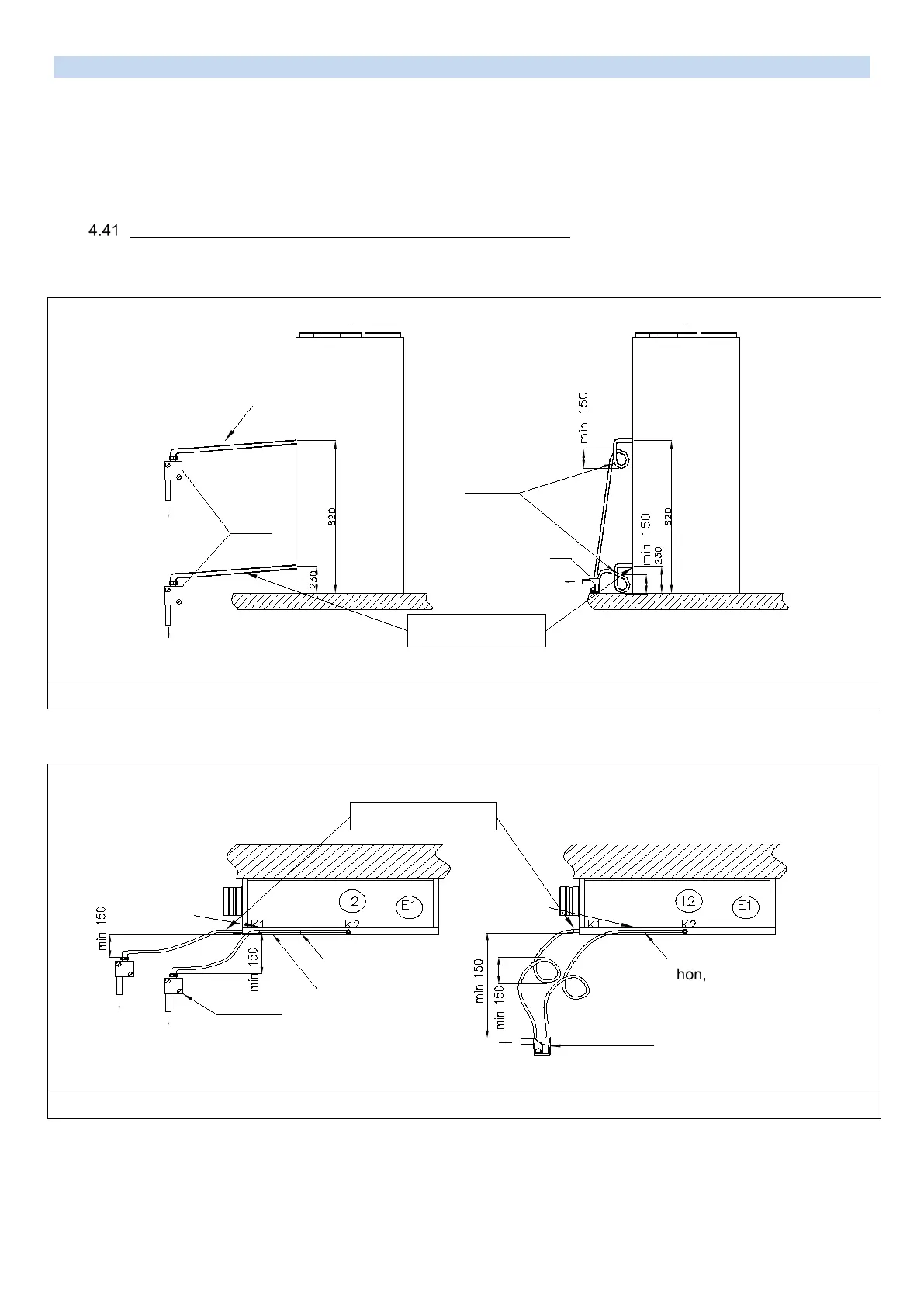
Condensate drain arrangement in RA5 and RK5 units.
Condensate drain arrangement in RB5 units.
Siphon HL 138 with mechanical odor trap
Siphon made of the flexible pipe
Make a siphon,
secure with
a clasp and fill
the water
Both condensate drains
can be connected to one
outlet behind the siphon!
To be fitted only for cooling
Siphon HL 138 with mechanical odor trap Siphon made of the flexible pipe
Make a siphon,
secure with a clasp
and fill the water
Flexible pipe to
placed hor
i
zontally
along the unit door
To be fitted only for cooling