EasyManua.ls Logo

ATREA DUPLEX RA5 - 3. Description and Technical Data; 3.1 Technical Parameters

ATREA DUPLEX RA5
48 pages
Print Icon
To Next Page IconTo Next Page
To Previous Page IconTo Previous Page
Loading...
7
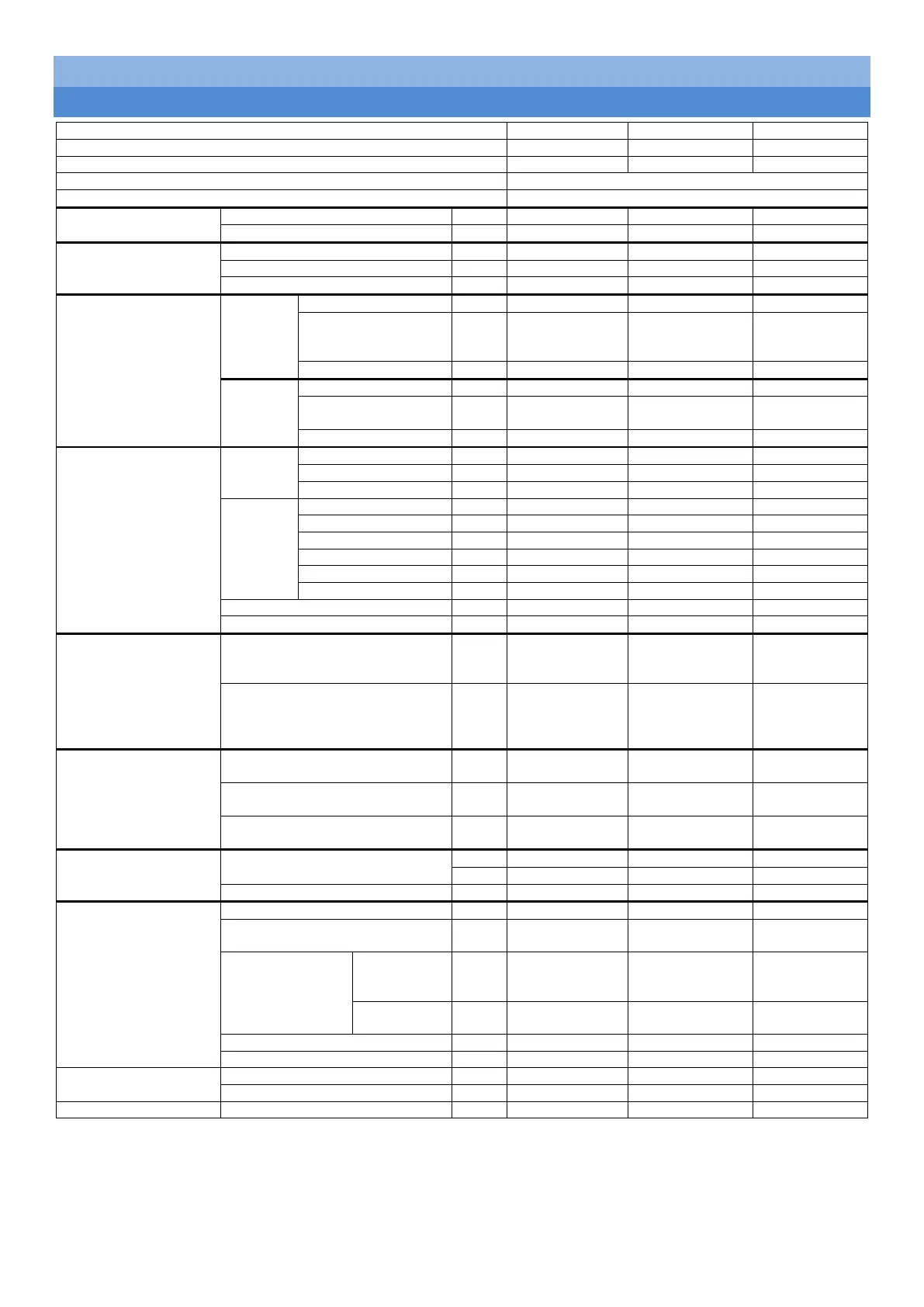
3. Description and technical data
3.1 Technical parameters
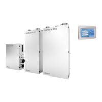
DUPLEX unit identification
RA5
RB5
RK5
Ordering code
A170421
A170431
A170441
Energy label
A
1)
A
1)
A
1)
Control system
RD5.CF
Outside air temperature sensor (ADS 110)
Included
Main power supply
Connecting voltage
[V]
230 V / 50 Hz
230 V / 50 Hz
230 V / 50 Hz
Required protection
[A]
10 A char. C
10 A char. C
10 A char. C
Heat recovery
exchanger
Type
[-]
S3.B
S3.B
S3.B
Efficiency (dry)
[%]
78
79
78
Block height
[mm]
275
275
275
Fans
Supply
Type
[-]
M106
M106
M107
Recirculation air flow
rate
(max. power)
[m
3
/h]
600 m
3
/h
600 m
3
/h
1200 m
3
/h
Power input for sizing
[W]
170 W
170 W
385 W
Exhaust
Type
M104
M104
M104
Ventilation flow rate
(max. power)
[m
3
/h]
350 m
3
/h
350 m
3
/h
350 m
3
/h
Power input for sizing
[W]
120 W
120 W
120 W
Design
Dimensio
ns
Height
[mm]
1720
1180
1720
Width
[mm]
675
900
865
Depth
[mm]
630
380
630
Duct
connectio
n collars
SUP-top (e2)
[mm]
Ø200
Ø200 (110x295)
Ø250
SUP-bottom (e2)
[mm]
460×460
-not included-
460×460
ODA (e1)
[mm]
Ø200
Ø200
Ø250
ETA (i1)
[mm]
Ø160
Ø160
Ø160
EHA (i2)
[mm]
Ø160
Ø160
Ø160
RCA (c1)
[mm]
Ø200
Ø200
Ø250
Weight with 1 exchanger
[kg]
115
87
125
Weight with 2 exchanger
[kg]
125
97
135
Integrated exchanger
(heating)
Hot water coil, 3 rows (T.3) [-]
TRA 3R / typ1
(20-322501)
TRB 3R / typ1
(20-322103)
TRK 3R / type
1
(20-322501)
Electric heater (E) [-]
ELO PTC RA
6600 W / 400 V
(separate
protection)
ELO PTC RB
4400 W / 400 V
(separate
protection)
ELO PTC RK
6600 W / 400 V
(separate
protection)
Integrated exchangers
(cooling)
Water coil, 3 rows (CHW.3)
[-]
WRA 3R / type 1
WRB 3R / type 1
WRK 3R / type
1
Water coil, 5 rows (CHW.5)
[-]
WRA 5R / type 1
WRB 5R / type 1
WRK 5R / type
1
Direct heat exchanger, 3 rows
(CHF)
[-]
CHF RA3
CHF RB3
CH RK3
Duct exchangers
(heating)
Electric heater (EPO-V)
[-]
EPO-V 200/2,1
EPO-V 200/2,1
EPO-V 250/3,0
[-]
EPO-V 250/3,0
EPO-V 250/3,0
EPO-V 315/6,0
Electric pre-heater (EPO-V)
[-]
EPO-V 160/1,6
EPO-V 160/1,6
EPO-V 160/1,6
Cold / heat source
(condensation unit)
Recommended type
FG14
FG09 / FG14
FG14 / FG18
Power supply and recommended
protection
230 V / 16 A
230 V / 16 A
230 V / 16 A
Refrigerant supply
connection
To
condensatio
n unit
12.7×6.35
9.52×6.35 /
12.7×6.35
12.7×6.35
To heat
exchanger
12.1×6.1
10.1×6.1 /
12.1x6.1
12.1×6.1
Refrigerant type
R410A
R32 / R410A
R410A
Cooling / heating capacity
[-]
Selection SW
Selection SW
Selection SW
Filters
Supply air (i.e. RCA + SUP)
G4/F7
G4/F7
G4/F7
Exhaust air (i.e. ETA)
G4
G4
G4
Controller
CP Touch
CP Touch
CP Touch
*) The values must be configured according to the individual capacity graph lines.
1) All control systems integrated in the unit include as a standard feature at least two inputs for connecting electric signals resulting
from human activity such as handling light fixtures or other devices which automatically control the unit’s capacity levels. These
inputs must always be connected; alternatively, other types of sensors must be connected instead (e.g. CO
2
, VOC and RH).
For the detailed design of individual components use ATREA’s selection software.

Table of Contents

Related product manuals