4
6.7
Breakdowns, safety instructions ..................................................................................................................................... 40
7. Faults and troubleshooting ............................................................................................................................................. 41
7.1 Faults and troubleshooting ............................................................................................................................................. 41
8. Appendices..................................................................................................................................................................... 42
8.1 Product data sheet ......................................................................................................................................................... 42
8.2 RD5 wiring diagram – internal wiring .............................................................................................................................. 43
8.3 RD5 wiring diagram - optional accessories ................................................................................................................... 44
1.3 Introduction
The manual is intended solely for ATREA’s DUPLEX RA5, RB5 and RK5 balanced-pressure recirculating ventilation units including
built-in RD5 control modules and a heat / cold exchanger.
1.4 Description of the unit
It is a compact, recirculating ventilation unit with a heat recovery feature and built-in exchangers. The unit consists of a casing,
a pair of fans, a heat recovery exchanger, heating and cooling exchangers, a built-in control module, a bypass damper,
a recirculating air damper, filters, thermostats and sensors.
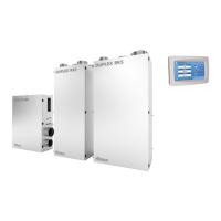
DUPLEX RA5 – units designed for free-standing installation only; duct connection collars must be specified
DUPLEX RB5 – units designed for ceiling-suspended installation only; versatile configuration
DUPLEX RK5 – units designed for free-standing installation only; duct connection collars must be specified
Collectively, this group of units is referred to as DUPLEX R5.
1.5 Abbreviations, marking
- Supply of fresh air from the outside into the unit
- Supply of fresh air after heat recovery into the building or supply of thermally conditioned recirculated air back
into the building
- Intake of waste air from the building into the unit
- Waste air exhaust from the unit to the outside
- Intake of recirculated air into the unit for thermal conditioning
1.6 Important information
• DUPLEX heat recovery ventilation units are designed for comfort ventilation, heating and cooling in standard environments
(CSN 33 2000-5-51) with relative humidity up to 90%. If the unit should be used for different purposes (e.g. drying newly
constructed buildings, dust extraction etc.) or not operated in keeping with the instructions contained in the use and
maintenance manual, the producer shall not be held liable for any resulting damage.
• The units may only be installed indoors within the heat envelope of residential buildings.
• Only adults sufficiently familiar with the “Installation, use and maintenance manual” may operate the unit.
• The user must not tamper with or modify any part of the unit, particularly the power supply lines! The unit must not be used
for drying construction sites or for dust, building material or other solid particle extraction.
• Only professional service technicians with relevant qualifications may perform the commissioning and repairs of the unit.
Unprofessional maintenance and repairs are very risky and may result in loss of warranty.
• Every time before opening the unit’s door in order to perform cleaning, replace filtration fabric or carry out basic mainte-
nance make sure the unit is disconnected from the power supply and ensure it cannot be reconnected by another person.
• Air ductwork of at least 2 metres in length must be attached to the unit on the fan discharge side as a means of protection
against injury caused by the fan wheel. This ductwork must be attached to the unit in such a way so it can only be removed
by using tools.
• The unit may only be installed in places where temperature does not drop below 10 °C and relative humidity is up to 60 % at
20 °C.
• If the unit has been out of operation for a prolonged period of time, extra care should be taken when putting it back into
operation.
• The unit – intended for standard environments – may be operated within a ventilation air temperature range of between
-25 °C and 45 °C and relative humidity up to 90%, in an environment where there is no risk of fire or explosion of flammable
gases or fumes containing organic solvents or corrosive substances that might damage mechanical parts of the unit. If there
is a danger of such gases and fumes temporarily entering the tube system (e.g. during floor bonding, painting), the unit must
be switched off sufficiently ahead of time.
• Electrical connections, commissioning and adjustment of the unit may only be carried out by appropriately qualified electrical
engineers. The unit must be protected using a 1×10 A char. C circuit breaker.
• If additional protection against touching active and inactive parts is provided by a residual-current circuit breaker, a special
residual-current device designed for circuits with frequency converters and switched-mode power supplies must be used. It
is a circuit breaker sensitive to alternating, pulse and residual currents and resistant to current surges of up to 5 kA