21
5. Instrumentation and control, electrical wiring
Any work on the control system (replacing / removing sensors, checking connections of individual parts etc.)
must be done when the system is not live (after disconnecting the power supply)!
5.1 RD5 control system with CP Touch controller
The CP Touch controller can be connected to DUPLEX units fitted with an RD5 control panel. The CP Touch provides
comprehensive control for these units, i.e. user and service parameter settings (password-protected). It has a manual mode,
through which the user directly selects the unit’s operation, or a weekly mode, which controls the unit using weekly program
settings. The software version is also indicated by the controller in user settings (6.8).
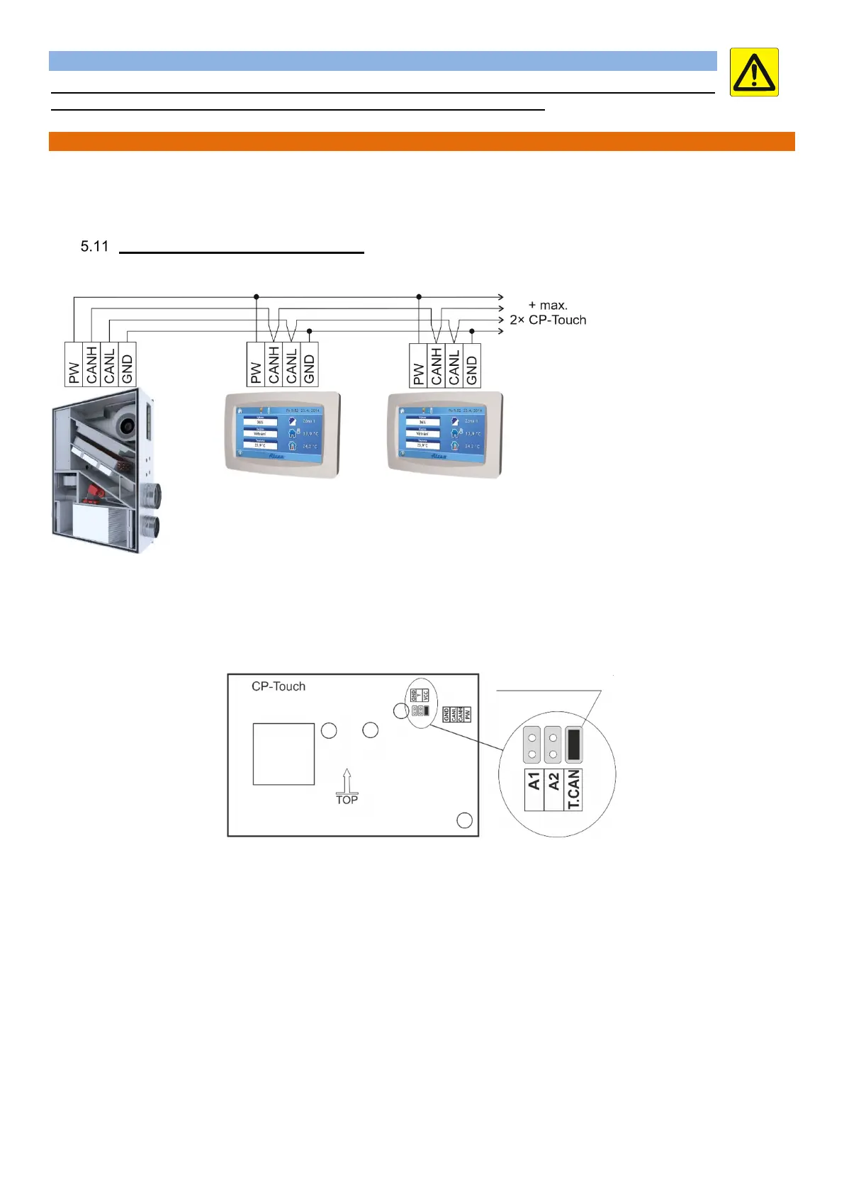
Connecting the controller to the unit
Connect the controller wiring following the wiring diagram enclosed in the AHU’s electrical panel. If more controllers are connected,
they must be connected to each other in series.
Note
According to the diagram there can be up four controllers connected to a single unit with RD5 control system. The last controller
connected to the bus bar must have an activated termination resistor – jumper short circuit.
The back of the controller board has jumpers at designated points as shown in Fig. 2 and 3:
T.CAN – A termination resistor jumper; the jumper must be fitted on the last controller in line.
A1 – 1
st
controller addressing jumper
A2 – 2
nd
controller addressing jumper
The jumpers of each controller on the same bus bar must have a different address.
The table shows controller connection options. When more controllers are installed, their addressing must be different. The last
controller in the series must be terminated with a Number jumper.
jumper with
termination resistor