32
Connector Panels
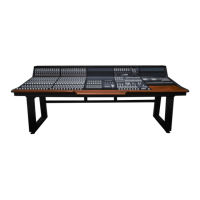
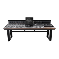
The Connector Panels are the points at which the
ASP8024-HE connects to the rest of the Studio.
The inputs and outputs use advanced, electronically
balanced or ground sensing topologies and are
fitted with extensive RFI rejection networks.
All signal interfaces are also fully protected against
accidental misuse, e.g. by the connection of
phantom powered cables.
We use high quality Neutrik™ XLR connectors and
Cli™ TRS Jacks for all the connections to ensue
that your signal quality is never compromised.
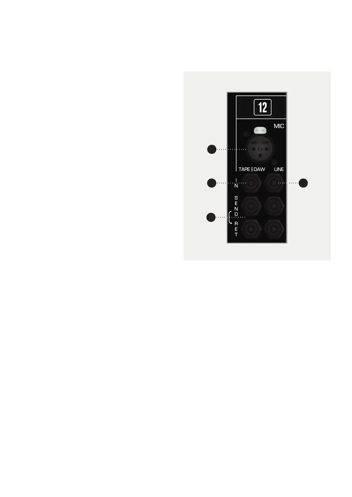
The rear mounted Connector Panel is where the
input, output and insert point connectors are
located.
The Microphone Input uses an XLR Connector, while
the Line Input, Tape Input and the Insert Sends and
Returns use Tip, Ring and Sleeve jacks.
NOTICE
Please note that if you have the Patchbay module
fitted, the rear Connector Panel will only have the
Mic and Line Inputs; the inserts and Tape/Daw
Returns can be accessed via the patchbay module.
For more information, please see the Patchbay
Section of this manual.
1 MIC Microphones or other low level equipment can
be connected to this input.
2 LINE The Line Input can be selected in place of the
Microphone Input. This input is designed for higher,
line level signals.
3 TAPE/DAW INPUTS The output of your converters/
tape machine should be connected here. This input
is designed for line level signals.
4 SEND / RET There are two insert points per channel,
with the Tape/DAW Insert on the left and the Mic/Line
Insert on the right.
The Insert Points are half-normalled so the sends
can be used as extra outputs without breaking the
signal path. Plugging a jack into the return breaks the
signal path so be careful not to plug a jack in without
a piece of gear attached.
Please note that the insert points aren’t aected by
the Flip Switch.
1
3
4
2
 Loading...