35
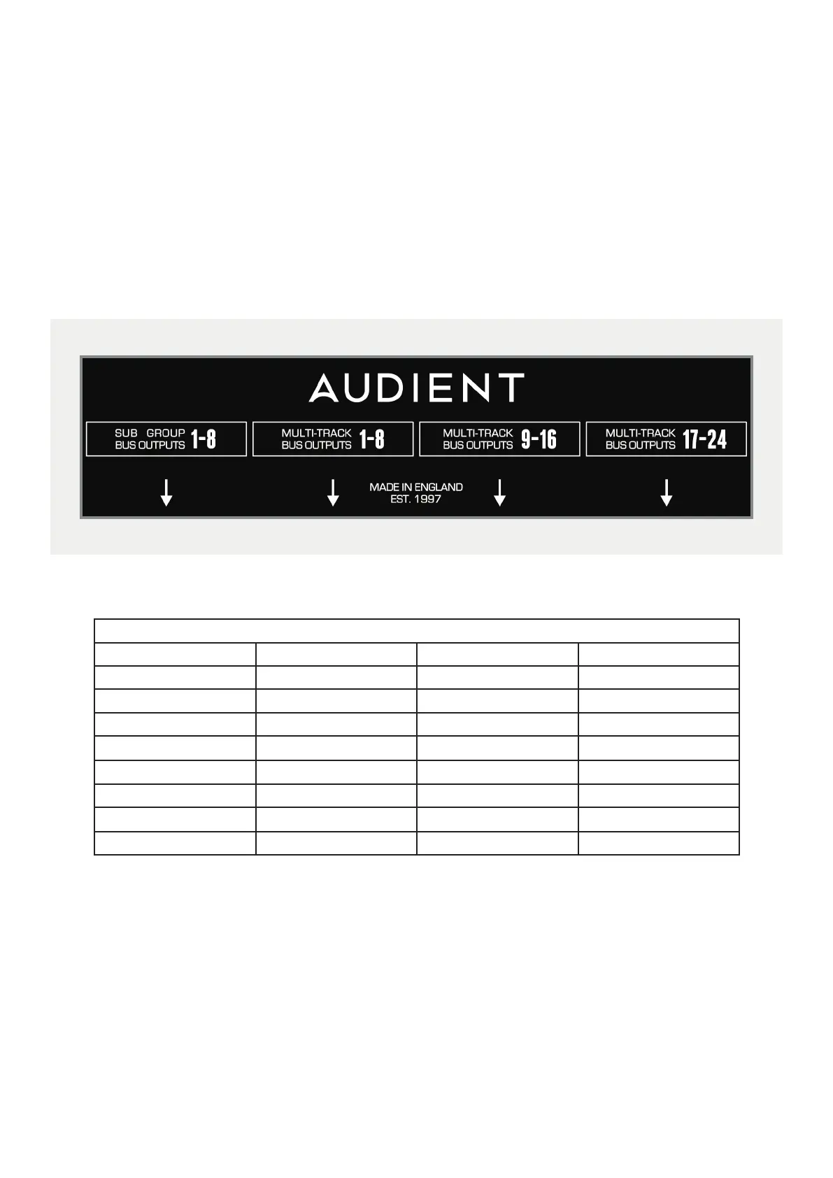
Connector Panels
This panel contains the connectors for the Multi-track Bus Outputs. Rather than having individual connectors for each
output, multi-pole connectors are used for fast and easy installation.
The Multi-track Bus Outputs are split across 3 connectors, each carrying the outputs for 8 tracks. The Sub Group
Outputs are on a fourth connector. All of the connectors follow the Tascam DB25 wiring standard.
MULTIPIN CONNECTIONS
SIGNAL NUMBER +VE SIGNAL VE SIGNAL SCREEN
1 / 9 / 17 24 12 25
2 /10 /18 10 23 11
3 / 11 / 19 21 9 22
4 / 12 / 20
7
20
8
5 / 13 / 21 18 6 19
6 / 14 / 22 4 17 5
7 / 15 / 23 15
3
16
8 / 16 / 24 1 14 2
NOTE: All undesignated pins are unconnected. All screen connections are joined inside the console and
connected to metalwork earth.
PATCHBAYS: Tie lines connections 25-32 etc follow the same wiring convention shown above.