MSBR Series 37 Mediant 800 MSBR
Hardware Installation Manual 6. Cabling the Device
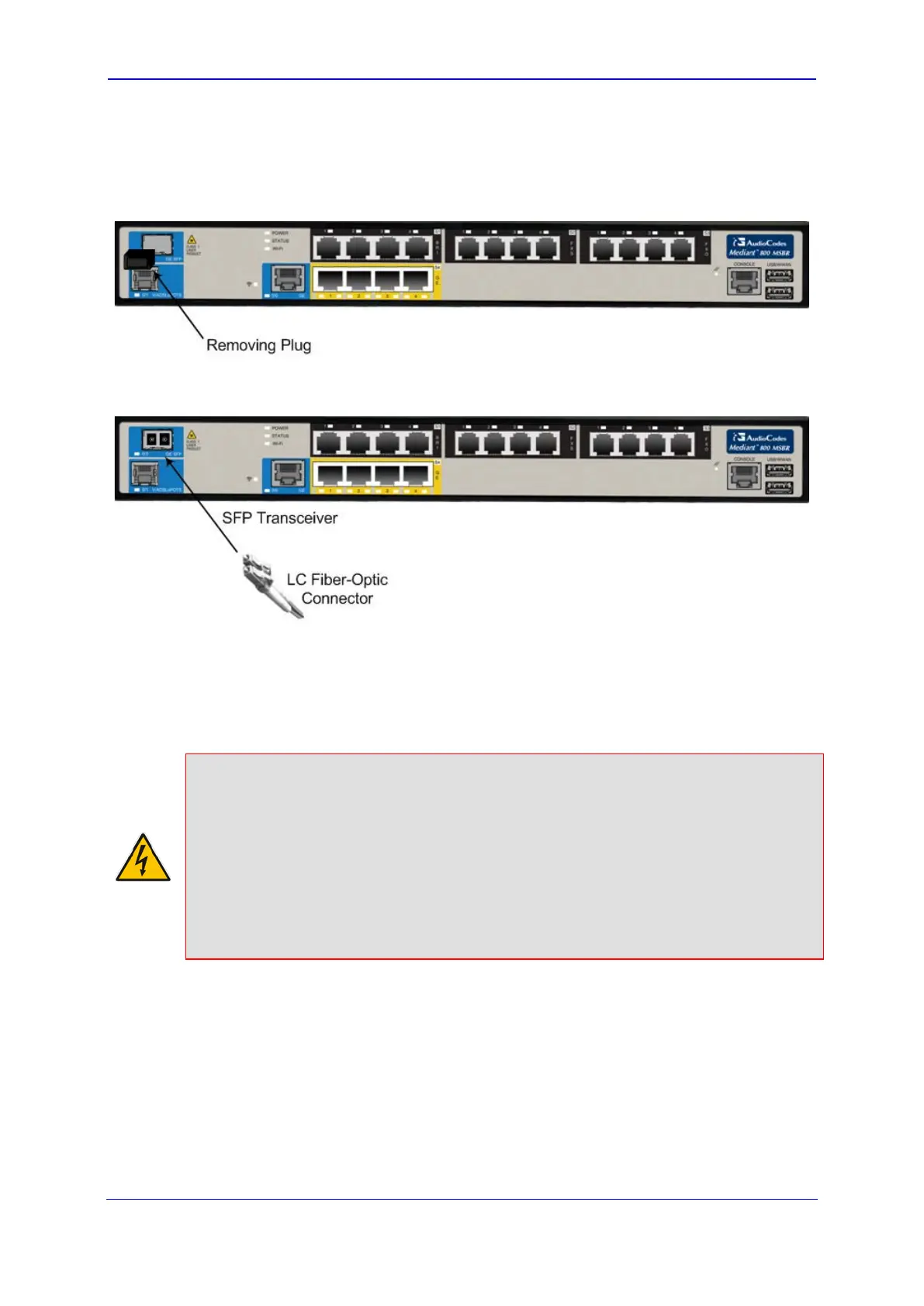
To connect the fiber-optic WAN GbE port:
1. Remove the protective dust plug from the SFP transceiver module.
Figure 6-3: Removing Protective Dust Plug
2. Connect a cable with LC-type plugs to the SFP transceivers (labeled GE SFP).
Figure 6-4: Cabling the Fiber-Optic WAN GbE Port
6.2.3 SHDSL WAN Cabling
Each SHDSL port provides up to four wire-pairs, which can support up to two RJ-11
physical connectors.
Warnings:
• The device does not include primary telecom protection! When the DSL telephone
lines are routed outside the building, additional protection - usually a 350V three-
electrode Gas Discharge Tube (GDT) as described in ITU-T K.44 - must be provided
at the entry point of the telecom wires into the building (usually on the main
distribution frame / MDF), in conjunction with proper grounding. The center pin of the
GDT (MDF grounding bar) must be connected to the equipotential grounding bus bar
of the Telecommunication room.
• To protect against electrical shock and fire, use a minimum 26-AWG wire to connect
the DSL ports.
SHDSL port specifications:
Conforms to ITU G.991.2 Annexes A, B, E, F and G SHDSL
Up to 5,696 Kbps over a single wire pair
Up to 22,784 Kbps over four wire pairs bonding, according to SHDSL.bis (ITU G.991.2
Annexes F, G)
EFM and ATM support
Wetting current support on the CPE side, according to G991.2

 Loading...


