Hardware Installation Manual 16 Document #: LTRT-10229
Mediant 800 MSBR
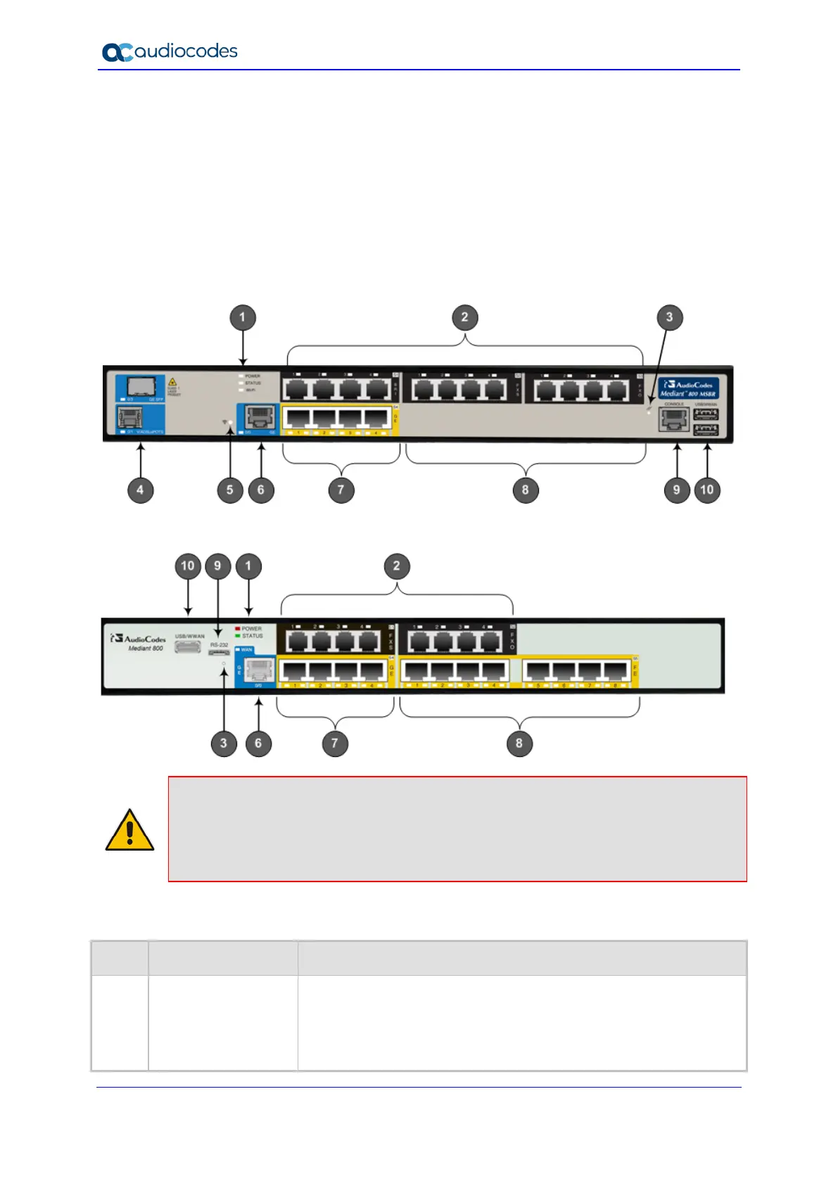
3.2 Front Panel Description
The front panel provides the telephony port interfaces, various networking ports, reset
pinhole button, and LEDs.
3.2.1 Ports and Buttons
The device's front panel is shown in the figure below and described in the subsequent
table.
Figure 3-1: Front Panel of Mediant 800B MSBR
Figure 3-2: Front Panel of Mediant 800A MSBR
Notes:
• The figures above are used only as examples; the number and type of port interfaces
depends on the ordered model.
• For available hardware configurations, please contact your AudioCodes sales
representative.
Table 3-2: Front-Panel Description of Ports and Buttons
Item # Label Description
1 POWER / STATUS /
Wi-Fi
LEDs indicating the status of the power, reboot/initialization, and
Wireless LAN interface. For more information, see Section 3.2.2 on
page 19.
Note: The Wi-Fi LED is available only for models ordered with Wi-Fi
functionality.

 Loading...


