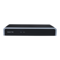
MSBR Series 5 Mediant 800 MSBR
Hardware Installation Manual Contents
List of Figures
Figure 3-1: Front Panel of Mediant 800B MSBR ................................................................................... 16
Figure 3-2: Front Panel of Mediant 800A MSBR ................................................................................... 16
Figure 3-3: Rear Panel .......................................................................................................................... 24
Figure 4-1: Attaching Antennas on Rear Panel ..................................................................................... 27
Figure 5-1: Location for Applying Rubber Feet ...................................................................................... 29
Figure 5-2: Mounting Brackets ............................................................................................................... 31
Figure 5-3: Attaching the Mounting Brackets ........................................................................................ 31
Figure 6-1: Earthing the Device ............................................................................................................. 34
Figure 6-2: Cabling the WAN Copper GbE Port .................................................................................... 36
Figure 6-3: Removing Protective Dust Plug .......................................................................................... 37
Figure 6-4: Cabling the Fiber-Optic WAN GbE Port .............................................................................. 37
Figure 6-5: Cabling the SHDSL WAN Port ............................................................................................ 38
Figure 6-6: Cabling xDSL WAN Port ..................................................................................................... 40
Figure 6-7: RJ-45 Connector Pinouts for E1/T1 WAN ........................................................................... 41
Figure 6-8: Splitter Cable for Single E1/T1 WAN Port ........................................................................... 41
Figure 6-9: Connecting the E1/T1 WAN Port ........................................................................................ 41
Figure 6-10: Plugging the 3G Cellular Modem into the USB Port ......................................................... 42
Figure 6-11: Cabling the LAN Ports ....................................................................................................... 43
Figure 6-12: RJ-11 Connector Pinouts for FXS Interface ...................................................................... 45
Figure 6-13: Connecting FXS Interfaces ............................................................................................... 45
Figure 6-14: RJ-11 Connector Pinouts for FXO Interface ..................................................................... 46
Figure 6-15: Connecting FXO Interfaces ............................................................................................... 46
Figure 6-16: RJ-11 Connector Pinouts for FXS Lifeline ........................................................................ 47
Figure 6-17: Cabling FXS Lifeline .......................................................................................................... 47
Figure 6-18: RJ-45 Connector Pinouts for BRI Ports ............................................................................ 48
Figure 6-19: Cabling BRI Ports .............................................................................................................. 48
Figure 6-20: Cabling (Ports 1 and 2) PSTN Fallback ............................................................................ 49
Figure 6-21: RJ-48c Connector Pinouts for E1/T1 ................................................................................ 50
Figure 6-22: Cabling E1/T1 Ports .......................................................................................................... 50
Figure 6-23: RS-232 Cable Adapter ...................................................................................................... 51
Figure 6-24: Orderable RS-232 Cable Adapter ..................................................................................... 52
Figure 6-25: Cabling Serial Interface (RJ-45) on Mediant 800B MSBR ................................................ 53
Figure 6-26: Cabling Serial Interface (12-pin female LX40-12P Hirose) on Mediant 800 MSBR .......... 53
Figure 6-27: Connecting USB Storage Device ...................................................................................... 54
Figure 6-28: Cabling OSN Server Ports ................................................................................................ 56
Figure 6-29: Connecting to the Power Supply ....................................................................................... 57
Figure 7-1: Opening the Fuse Cavity ..................................................................................................... 59
Figure 7-2: Removing the Power Fuse .................................................................................................. 59
 Loading...


