9.5 Valve Proving
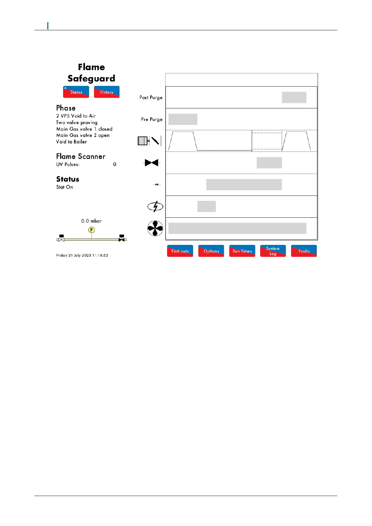
Figure 9.5.i VPS Venting
In this example, the Flame Safeguard controller has no vent valve and has single valve pilot optioned. 2 Valve proving
is used to check the integrity of the gas for any leaks. See option/parameter 130.
During the VPS Venting phase shown in Figure 9.5.i., the main gas valve 1 is checked. The main gas valve 1 output
is off (closed), and the main gas valve 2 output is on (opened), so that the void between the main gas valves can
vent to atmosphere.
The gas pressure sensor is now zeroed. If the gas pressure sensor cannot be zeroed, the lockout ‘VPS air zeroing
fail’ will occur, since the gas pressure has been detected when venting to atmosphere. This could indicate that there
is a fault with the main gas valve 1 or 2.
If no voltage is detected when the burner main gas valve 2 output T61 should be on (and vice versa), the lockout
‘Main Gas 2 Output Fault’ will occur.
Note: If valve proving has been optioned with no vent valve and with single valve pilot, then the pilot valve is used
for this VPS venting phase.

 Loading...