EasyManuals Logo

AUTOFLAME MK8 User Manual

AUTOFLAME MK8
150 pages
To Next Page IconTo Next Page
To Previous Page IconTo Previous Page
Page #27 background imageLoading...
Page #27 background image
2
Options & Parameters
Flame Safeguard (MM80001/FSG) Manual
Page | 33
1.6.2
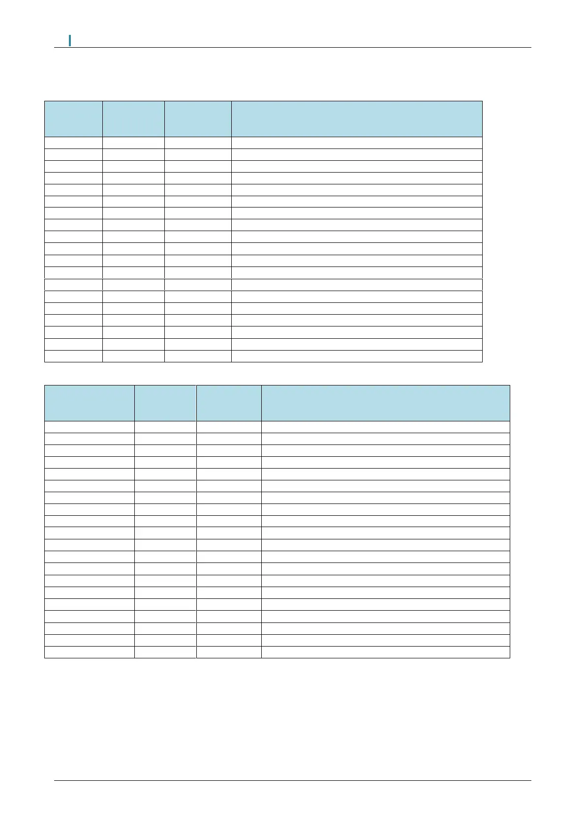
Converting Fireye Flame Safeguard Units
1.6.2.1 Fireye E110:
Firey e
Term inal
# (E110)
Autoflam e
FSG
Term inal #
Ty pe
Description
L1
68
Input
HOT 120 VAC
L2
67
Input
GROUND NEUTRAL
-
66
Input
EARTH GROUND
S1
-
1
Input
SCANNER (+)
S2
-
1
Input
SCANNER (-)
3
55
Output
PRE-IGNITION INTERLOCKS (FUEL VALVE END SWITCH)
M
58
Output
BLOWER MOTOR
D
80
Input
LOW FIRE START INTERLOCK
P
54
Input
RUNNING INTERLOCKS (AIR FLOW SWITCH)
5
2
63
Output
5 SEC EARLY SPARK TERMINATION
6
2
59
Output
10 SEC INTERUPTED PILOT
7
60, 61
3
Output
MAIN FUEL VALVE
8
81
Input
OPEN DAMPER PURGE INTERLOCK
A
79
4
Output
ALARM
X
B/B1
5
Output
MODULATION HIGH FIRE
10
R
5
Output
MODULATION COMMON
11
R1
5
Output
AUTO MODULATION
12
W/W1
5
Output
MODULATION LOW FIRE
13
53
Input
OPERATING CONTROL INTERLOCK
1.6.2.2 Fireye Burnerlogix:
Firey e Term inal
#
(BURNERLOGIX )
Autoflam e
FSG
Term inal #
Ty pe
Description
L1
68
Input
HOT 120 VAC
L2
67
Input
GROUND NEUTRAL
E
66
Input
EARTH GROUND
S1
-
1
Input
SCANNER (+)
S2
-
1
Input
SCANNER (-)
3
53
Input
OPERATING CONTROL INTERLOCK
M
58
Output
BLOWER MOTOR
D
80
Input
LOW FIRE START INTERLOCK
P
54
Input
RUNNING INTERLOCKS (AIR FLOW SWITCH)
W
2
63
Output
IGNITION TRANSFORMER
5
2
63
Output
5 SEC EARLY SPARK TERMINATION
6
2
59
Output
10 SEC INTERUPTED PILOT
7
60, 61
3
Output
MAIN FUEL VALVE
8
81
Input
OPEN DAMPER PURGE INTERLOCK
A
79
4
Output
ALARM
X
B/B1
5
Output
MODULATION HIGH FIRE
10
R
5
Output
MODULATION COMMON
11
R1
5
Output
AUTO MODULATION
12
W/W1
5
Output
MODULATION LOW FIRE
13
55
Output
PRE-IGNITION INTERLOCKS (FUEL VALVE END SWITCH)
Notes
1: Any flame sensing device will need to be replaced with an Autoflame sensor. For more details, please see the Autoflame Flame
scanner guide.
2: The pilot configuration may vary for Terminals W, 5 & 6. Check which connects to the ignition transformer.
3: Terminal 60 = Main Fuel Valve 1, Terminal 61 = Main Fuel Valve 2. On Autoflame FSG.
4: Switched neutral output should be connected to neutral side of relay coil.
5: The connections shown assume the use of an Autoflame relay box. Please consult the wiring diagram, if alternative relays are used.

Table of Contents

Questions and Answers:

Question and Answer IconNeed help?

Do you have a question about the AUTOFLAME MK8 and is the answer not in the manual?

AUTOFLAME MK8 Specifications

General IconGeneral
BrandAUTOFLAME
ModelMK8
CategoryController
LanguageEnglish

Related product manuals