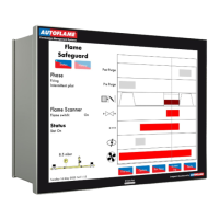
Autoflame Flame Safeguard Overview, Specifications and Wiring
Flame Safeguard (MM80001/FSG) Manual
Honey w ell
Term inal #
(EC7850A)
LINE VOLTAGE COMMON (NEUTRAL)
LIMITS AND BURNER CONTROL
PILOT VALVE 1 (INTERRUPTED)
PREIGNITION INTERLOCK INPUT
PILOT VALVE 2 (INTERMITTENT)
Notes
1: Any flame sensing device will need to be replaced with an Autoflame sensor. For more details, please see the Autoflame Flame
scanner guide.
2: Switched neutral output should be connected to neutral side of relay coil.
3: Terminal 60 = Main Fuel Valve 1, Terminal 61 = Main Fuel Valve 2. On Autoflame FSG.
4: The connections shown assume the use of an Autoflame relay box. Please consult the wiring diagram, if alternative relays are used.

 Loading...