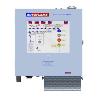
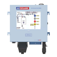
Autoflame Flame Safeguard Overview, Specifications and Wiring
Flame Safeguard (MM80001/FSG) Manual
1.5 Relay Box
The relay box (SP80070, SP80070/110) provides all the connections shown in section 1.3.1 for wiring between a
servo motor with high and low limit switches and the Flame Safeguard controller. It also provides for the switchover
of control to a load sensor allowing the burner to modulate once the flame has been established. The Flame
Safeguard unit will continue to monitor the status of the flame and initiate a safety shutdown in the event of any
issues.
PLEASE NOTE – THAT THERE ARE TWO DIFFERENT VERSIONS OF THE FLAME SAFEGUARD RELAY
ADAPTOR (230V & 110V). THE FOLLOWING PART NUMBER USED, FOR THESE VOLTAGES ARE SP80070
FOR 230V & SP80070/110 FOR 110V.
1.5.1
Relay Box Terminal Description
Mains voltage output, power to Relay Box (SP80070, SP80070/110).
Switched neutral – High/Low Initiate output.
Switched neutral – Release to Modulate output.
Connection to a controller (Common Voltage Input)
Connection to a controller (Common Voltage Input)
Connection to a controller (Common Voltage Input)
Connection to a motor (Common Voltage Input)
Connection to a motor (Common Voltage Input)
Connection to a motor (Common Voltage Input)
Fused mains voltage output (F1 in Relay box) – for end switches to the motor (the common for
T80 & T81)

 Loading...