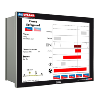
Autoflame Flame Safeguard Overview, Specifications and Wiring
Flame Safeguard (MM80001/FSG) Manual
1.4.7
Terminals Description
All terminals marked S are internally connected. They are provided for connections to the various
screened cables
Connections to an Autoflame self-check UV sensor
Communications port connections for Modbus
Digital communications connections to an Autoflame IR scanner
Digital communications connections to an Autoflame gas pressure sensor
0V supply to an Autoflame gas pressure sensor
+12V supply to an Autoflame gas pressure sensor
0V supply to an Autoflame IR scanner
+15V supply to an Autoflame IR scanner
Connections to an Autoflame UV scanner
Mains voltage input – external auxiliary delay to purge/ secondary proving set in option/parameter
157
Mains voltage input – burner on/off signal, running interlock circuit
Mains voltage input – air proving switch
Mains voltage input - proving circuits, e.g. gas valve proof of closure
Mains voltage input - lockout reset
Mains voltage output – call for heat
Mains voltage output – burner motor
Mains voltage output – start/pilot valve
Mains voltage output – main fuel valve 1
Mains voltage output – main fuel valve 2
Mains voltage output – vent valve
Mains voltage output – ignition transformer
Mains voltage output, power to Relay Box (SP80070, SP80070/110)
Switched neutral – High/Low Initiate output.
Switched neutral – Release to Modulate output.
Switched neutral – alarm output for MM lockout/MM error.
Low Fire / Start position interlock.
High Fire / Purge position interlock.

 Loading...