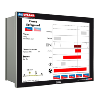
Flame Safeguard (MM80001/FSG) Manual
DTI: Warming Facility for Low Pressure Steam
For sequencing applications where non-return valves are not installed, it is
not possible to use a setpoint to keep the boilers in a standby condition. A
thermostat (aquastat) can be installed into the boiler’s shell. Set option 79
to 0 to enable terminal 93 for warming stat. An input on terminal 93
stops/inhibits the burner when the MM is in warming. The boiler will remain
in a warming state based on the settings in options 53
and 54.
Steam sequencing with non-return valves
Steam sequencing without non-return valves
For setting 0, the first lag boiler is kept in a standby state with the second
in warming, and the remaining lag boilers off. For setting 1, the first lag boiler
is in standby, and the remaining lag boilers are in warming.
All unused MMs in warming state
DTI: Standby Setpoint or Phantom Setpoint Offset
For sequencing applications where non-return valves are installed, the first
lag boiler uses a standby setpoint to keep the boiler in a standby condition.
The standby setpoint is set as an absolute value in this option. When the
standby setpoint is in effect, the burner is held at low flame hold.
O
C,
O
F, PSI or 0.1 bar or 0.01 bar for low pressure sensor (depends on
load detector set in option 1 and metric/imperial units set in parameter 40)
MM: Multi-Burner Function
The multi-burner function can be used for up to 10 burners, allowing the
firing rates to be synchronised for all the burners in the multi-burner loop.
For setting 1, if an error or lockout occurs on a burner, all of the other
burners will shut down; setting 1 is suitable for firetube boilers. For setting
2, if an error occurs on a burner, all of the other burners will shut down,
however if a lockout occurs, the other burners will continue to fire; setting
2 is suitable for watertube boilers. Fuel flow metering must be
commissioned accurately for the multi-burner function to operate. Please
refer to section 8 for commissioning of the multi-burner function.
When using the multi-burner function, the multi-burner IDs must be set on
the MMs This option should be set to 1 for the master, and 2 onwards for
the slave MMs.
When enabled, the internal PID control is disabled and the firing rate is set
by an external controller applied to the appropriate input terminals 7, 8, 9.
This input control signal can be 0-10V (2-10V) or 4-20mA (0-20mA) set
through parameter 69, and represent zero/low to high fire by setting
parameter 68. A manual reset high limit stat must be fitted. For setting 1,
an external working stat is required and option 9 should be set to 0. For
setting 2, option 9 should be set to 1 or 2. For setting 3 this permanently
limits the firing rate according to the input seen on the aux input channel.
Enabled, load sensor not shown
Enabled, load sensor shown

 Loading...