Page 5–14 Stellar
®
SR55 Series Soft Starter User Manual – 1st Ed, Rev F – 09/18/2019
Chapter 5: Communications
eTherneT/ip neTWork CommuniCaTions (ConTinued)
ConneCTing To The sr55-Cm-eneT module Through i/o (impliCiT messaging)
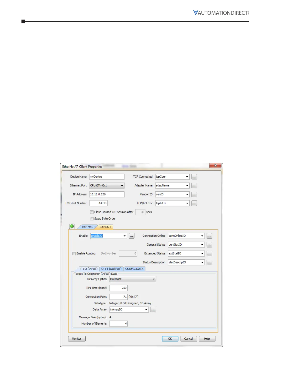
The connection parameters for Connection 6 (Extended Control) are as follows:
•
T->O (Input Data) Connection Point Assembly Instance value is 71.
•
T->O (Input Data) Size is 4 bytes.
•
The Data format for Status is shown in the “Input Data Setup” screen capture.
•
O->T (Output Data) Connection Point Assembly Instance value is 21.
•
O->T (Output Data) Size is 4 bytes.
•
The Data format for Control is shown in the “Output Data Setup” screen capture.
•
No Configuration data is required.
To start the SR55, a value of 33 should be placed into Byte 0 of the Control data.
33 equates to Bit 0 (Run Forward) On and Bit 5 (Net Control) On.
To stop the SR55, a value of 32 should be placed into Byte 0 of the Control data.
32 equates to Bit 0 Off and Bit 5 On.
To reset faults on the SR55, a value of 36 should be placed into Byte 0 of the Control data.
36 equates to Bit 2 (Fault Reset) On and Bit 5 (Net Control) On.
The following images are an example setup of I/O (Implicit Messaging) to the SR55 EtherNet/IP
adapter from a Productivity Series CPU.
inpuT daTa seTup

 Loading...