Chapter 2: Electrical Installation
Page 2–9Stellar
®
SR55 Series Soft Starter User Manual – 1st Ed, Rev F – 09/18/2019
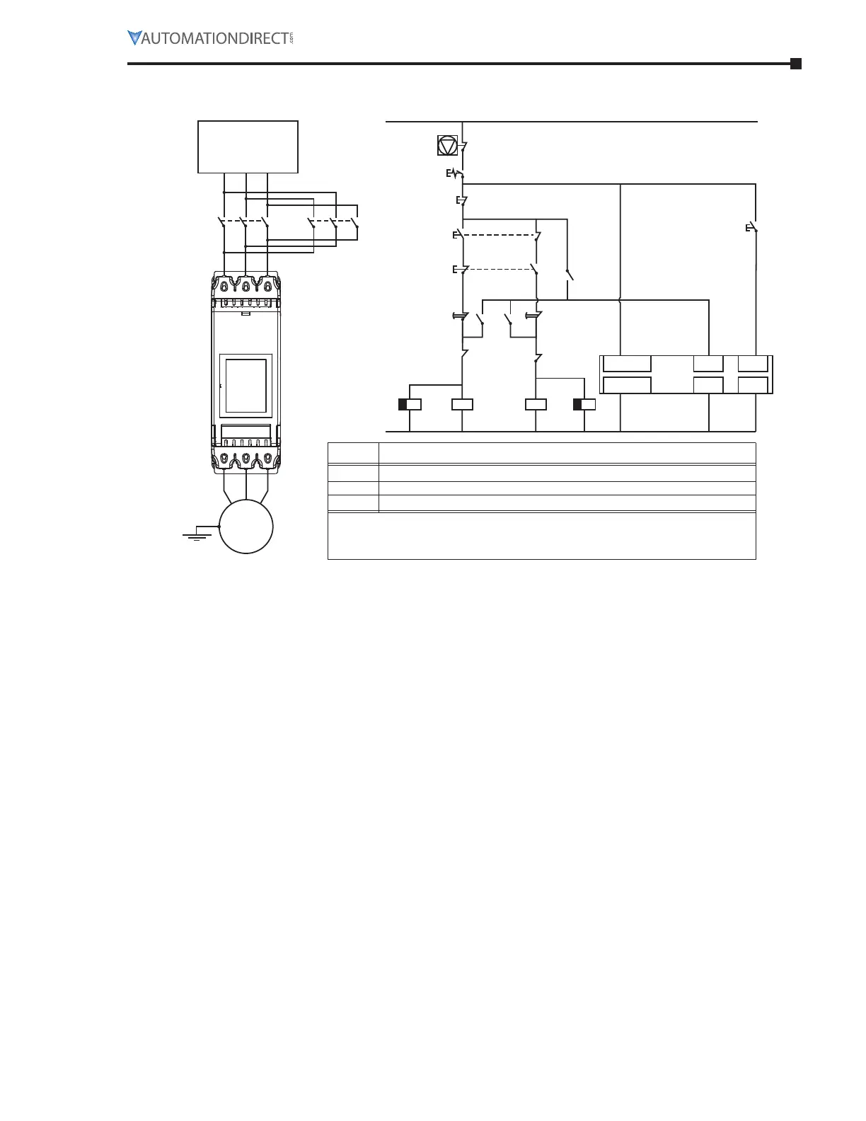
reversing Wiring diagram
!
Note: Forward and reverse buttons must remain pressed for longer than timer change over period.
K1 K2
Protection switch
gear (provided by
the customer)
Emergency Stop
Enable
Stop
Forward
Reverse
K2A
Induction
Motor
Control supply 110/230VAC or 24VDC
depending on application
K1 K2 K1A
K1
K1A K1 K2 K2A
Reset
33
SR55
34
SR55
D2-1ID1-1I
L or 24VDC
D2COMD1COM
N or 0VDC
K2
2/T1 4/T2 6/T3
1L1 3/L2 5/L3
Reversing Wiring Diagram
Item
K1, K2
K1A, K1B
SR55
These are the major components of the system. Local wiring regulations should be
observed. Note the use of timers to ensure that a reversed voltage is not applied to
the starter/motor before the motor eld has had some chance to die away.
Description
AC3 rated forward/reverse contactors
1-second o-delay timing relays (delay time must be ≥ the stop ramp time)
SR55-xxx soft starter
• “Stop” must be pressed before direction reversal can be initiated.
• Digital Output 3 must be congured to “Running.”
• Digital Input 1 must be congured to “High Start / Low Stop.”
• Digital Input 2 must be congured to “Reset.”

 Loading...