EasyManuals Logo

Automation Technology C5 Series User Manual

Automation Technology C5 Series
91 pages
To Next Page IconTo Next Page
To Previous Page IconTo Previous Page
Page #58 background imageLoading...
Page #58 background image
56
C5 Series User Manual Rev. 1.4
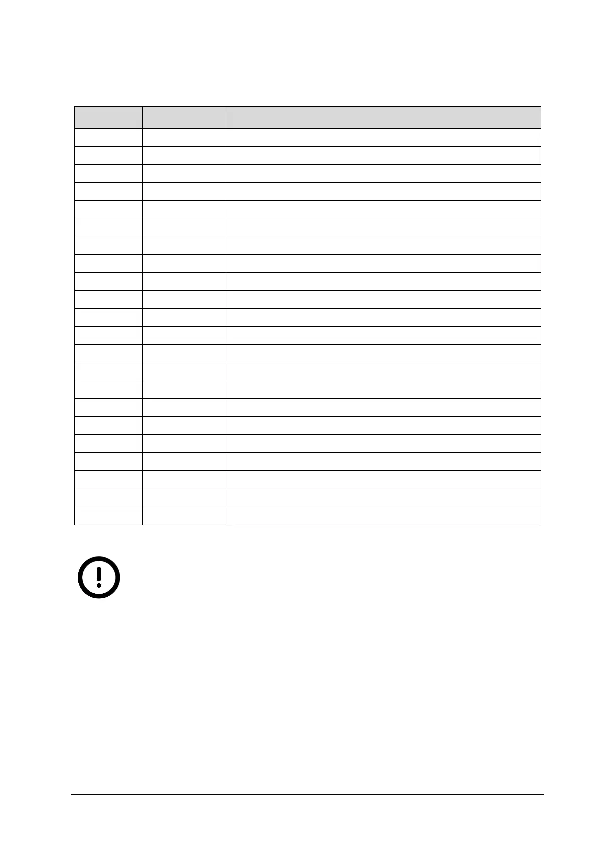
Clamp Configuration
Clamp No.
Signal Name
Description
J2/1
SHIELD
Camera shield
J2/2
GND_EXT ( - )
Camera supply ground
J2/3
GND_EXT ( - )
Camera supply ground
J2/3
VCC_EXT ( + )
Camera supply voltage (10-24V DC)
J2/4
VCC_EXT ( + )
Camera supply voltage (10-24V DC)
J3/1
Z-
Differential encoder/resolver index track Z-
J3/2
Z+
Differential encoder/resolver index track Z+
J3/3
B-
Differential encoder/resolver track B-
J3/4
B+
Differential encoder/resolver track B+
J3/5
A-
Differential encoder/resolver track A-
J3/6
A+
Differential encoder/resolver track A+
J3/7
RGND
Encoder/Resolver ground
J3/8
SHIELD
Encoder/Resolver shield
J4/1
IO_GND
Reference ground for digital inputs (IN1, 2) and outputs (OUT1, 2)
J4/2
OUT_Supply
Power supply voltage of camera isolated outputs (5-24V DC)
J4/3
OUT1
Isolated output #1 (reference voltage OUT_Supply)
J4/4
OUT2
Isolated output #2 (reference voltage OUT_Supply)
J4/5
IN1
Isolated input #1 (5-24V)
J4/6
IN2
Isolated input #2 (5-24V)
J5/1
SHIELD
Camera shield
J5/2
AGND
Analog output ground
J5/3
AOUT
Output for analog modulation of illumination device (05 V DC)
The analog output ground is directly connected to the internal camera
ground. The analog output is NOT electrically isolated from the device
ground! Please take care for a correct operation.

Table of Contents

Questions and Answers:

Question and Answer IconNeed help?

Do you have a question about the Automation Technology C5 Series and is the answer not in the manual?

Automation Technology C5 Series Specifications

General IconGeneral
BrandAutomation Technology
ModelC5 Series
CategoryAccessories
LanguageEnglish