EasyManuals Logo

Automation Technology C5 Series User Manual

Automation Technology C5 Series
91 pages
To Next Page IconTo Next Page
To Previous Page IconTo Previous Page
Page #71 background imageLoading...
Page #71 background image
C5 Series User Manual Rev. 1.4
69
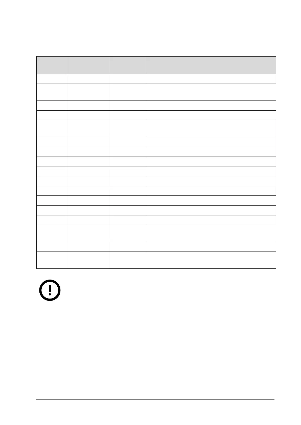
Wire Assignment of M12 17 pin Pigtail Cable
Pin/Wire
No.
Wire Colour
Signal
Name
Description
1
Brown
ENC_Z-
Encoder index track Z-
2
Blue
AO
Output for analog modulation of illumination
device (0 to +5V DC)
3
White
ENC_Z+
Encoder/Resolver index track Z+
4
Green
ENC_B+
Encoder/Resolver Track B+
5
Pink
GND
Reference GND for analog output AO (internal
camera GND)
6
Yellow
ENC_B-
Encoder/Resolver Track B -
7
Black
ENC_A-
Encoder/Resolver Track A -
8
Gray
VCC_EXT
Camera supply voltage (+10 to +24V DC)
9
Red
GND_EXT
Camera supply GND
10
Violette
ENC_A+
Encoder/Resolver Track A+
11
Gray/Pink
ENC_GND
Encoder/Resolver ground
12
Red/Blue
OUT2
Opto-isolated digital output 2
13
White/Green
IN1
Opto-isolated digital input 1 (+5 to +24V DC)
14
Orange/Green
IN2
Opto-isolated digital input 2 (+5 to +24V DC)
15
White/Yellow
OUT_Supply
Supply for digital output signals OUT1, 2 (+5 to +24V
DC)
16
Yellow/ Orange
OUT1
Opto-isolated digital output 1
17
White/Gray
IO_GND
Reference ground for digital inputs (IN1, 2) and
outputs (OUT1, 2)
The analog output ground is directly connected to the internal camera
ground. The analog output is NOT electrically isolated from the device
ground! Please take care for a correct operation.

Table of Contents

Questions and Answers:

Question and Answer IconNeed help?

Do you have a question about the Automation Technology C5 Series and is the answer not in the manual?

Automation Technology C5 Series Specifications

General IconGeneral
BrandAutomation Technology
ModelC5 Series
CategoryAccessories
LanguageEnglish