C5 Series User Manual Rev. 1.4
63
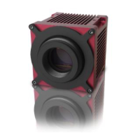
Master/Slave Connection
This schematic shows the required wiring to operate two C5 cameras in a Master/Slave
mode. For this purpose the OUT2 of the master camera is exemplary connected to the
trigger input IN1 of the slave camera. The Master/Slave mode can be realized with both
inputs (IN1/IN2) and outputs (OUT1/OUT2).
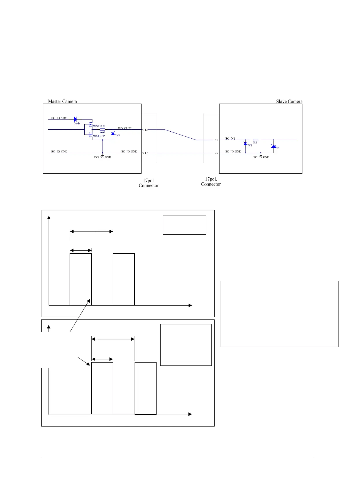
Example configuration for Master/Slave Connection
SLAVE
f=2500 Hz
Triggered after
exposure of
Master Sensor
The falling edge
of Master OUT2
generate a slave
profile trigger
Use Registers:
Master:
Output2 = Out2_IntegrationActive
Output2Invert = true
Slave:
ProfileTriggerMode = CameraInput1
 Loading...