24
COMPACT VOICE ALARM SYSTEM
SERVICE MANUAL
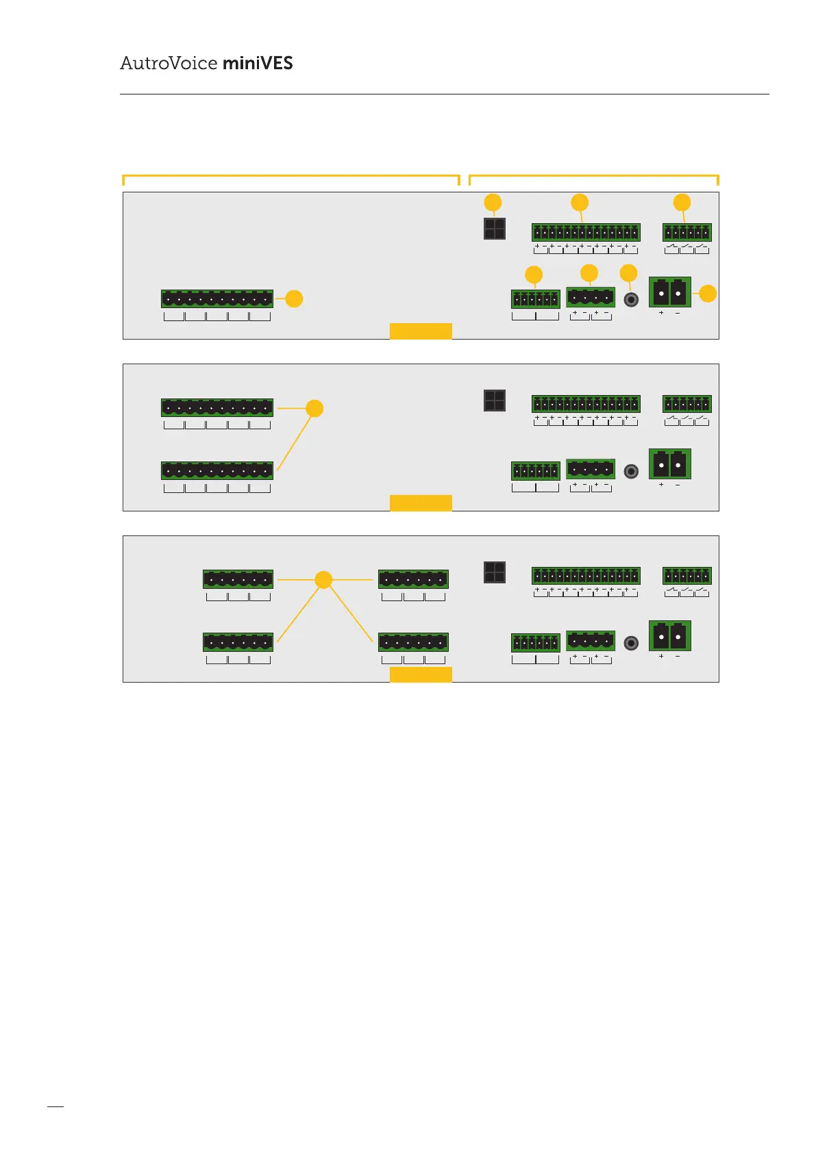
Drawing 4.
BUS1 BUS2
IN7IN6IN5IN4IN3IN2IN1
+48 VDC BATT
Audio IN Audio OUT
C
LR
C
LR
+24 VDC
150 mA
+48 VDC
350 mA
TEMP.
SENSOR
LINE ALINE BLINE CLINE DHV AUDIO IN
C
H
C
H
C
H
C
H
C
H
1
BUS1 BUS2
IN7IN6IN5IN4IN3IN2IN1
+48 VDC BATT
Audio IN Audio OUT
C
LR
C
LR
+24 VDC
150 mA
+48 VDC
350 mA
TEMP.
SENSOR
LINE ALINE BLINE CLINE DHV AUDIO IN
C
H
C
H
C
H
C
H
C
H
LINE ALINE BLINE CLINE DHV AUDIO IN
C
H
C
H
C
H
C
H
C
H
2
1
BUS1 BUS2
IN7IN6IN5IN4IN3IN2IN1
+48 VDC BATT
Audio IN Audio OUT
C
LR
C
LR
+24 VDC
150 mA
+48 VDC
350 mA
TEMP.
SENSOR
LINE ALINE BHV AUDIO IN
C
H
C
H
C
H
LINE ALINE BHV AUDIO IN
C
H
C
H
C
H
LINE ALINE BHV AUDIO IN
C
H
C
H
C
H
LINE ALINE BHV AUDIO IN
C
H
C
H
C
H
24
13
OUT3OUT2OUT1
OUT3OUT2OUT1
OUT3OUT2OUT1
2
Control Card slot
harger slots
5
8
1
6 7
43
9
10
2001 units
4001 units
4002 units
Line control card arrangement for AutroVoice miniVES systems
1. ABT xCtrLine-4 control card
2. Local audio bus outputs for 4 line control card operation
3. Logic inputs connector
4. Logic outputs connector
5. Audio I/O connector
6. Auxillary power outputs
7. Temperature sensor input jack
8. Main battery connector
9. Two ABT xCtrLine-4 control cards
10. Four ABT xCtrLine-2 control cards
Built in amplier module options:
1. 200X series units use two 160W amplier modules and a single switchable transformer. This enables one of the ampliers
towork as the main unit while the second one provides redundancy
2. 400X series units use two 320W amplier modules with two transformers. This enables both of the ampliers to work either
simultaneously with the total output limited to 320W or with one used as main and the other one as backup.
 Loading...