60
COMPACT VOICE ALARM SYSTEM
SERVICE MANUAL
7.3.2 Batteries
It is necessary to protect batteries from short-circuit while connecting battery leads. Short-circuit may lead to system failure.
Follow this manual to assure safety while connecting.
Make sure the system power has been switched o before battery is connected.
Once the batteries have been connected, make sure all terminals of all batteries have been protected against short-circuit.
Connecting batteries
» Wait over 10 seconds after the power cord was unplugged from AC socket located on the AutroVoice miniVES main unit.
»
Never connect negative cable in the rst place as in the case of short-circuit between battery positive wire and a device
frame or rack cabinet element, a device damage may occur.
» Connect battery negative cable to negative terminal.
Disconnecting batteries
»
Make sure battery supply is not used. To do so, check LED on the AutroVoice miniVES front panel which signals such state of aairs.
» Take out battery negative lead from terminals. Neverdisconnect positive wire in the rst place as it may cause short-circuit
if you touch device frame or rack cabinet elements. Isolate disconnected cable tip with a suitable insulator, e.g. insulating
tape, to protect against short-circuit.
»
Disconnect last battery lead. Isolate disconnected wire tip with a suitable insulator, e.g. insulating tape, to protect
against short-circuit.
c
A total voltage of batteries connected to the device, loading and monitoring, according to EN 54-4 should reach 48V DC
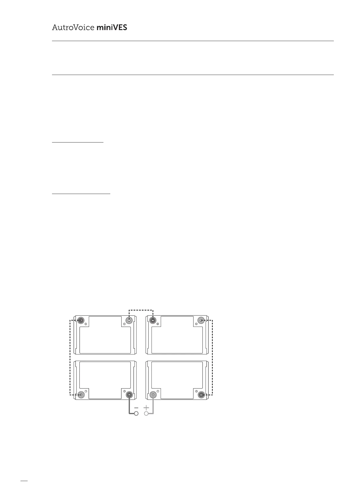
(40-56V DC). In the last stage of system comissioning, it is necessary to connect four VRLA 12 V batteries to the battery port
located on the main connector panel of the AutroVoice miniVES unit via the provided cable with special regard to wire
polarity. Additionally, it is necessary to connect a thermistor temperature sensor by connecting its wire to Temp Sensor
connector and placing the sensor in the place where the batteries were installed.
Drawing 35. 4x12 V DC VRLA storage batteries connecting diagram
 Loading...